MarkRSpear
Plastic
- Joined
- Mar 27, 2014
- Location
- Indiana, USA
I'm installing an Hitachi WJ200-015 VFD on a small turret lathe a LHT-25b (Lin Huan variety).

This lathe has a threading feature that I would like to use. I have not used this lathe, or any turret lathe for that matter, so my information is from the manual and looking at the machine.
If I use incorrect terminology for the machine functions that’s why.
The lathe has two momentary contact switches for FORWARD and REVERSE as the turret is cycled through the threading station.
The vfd has what seems to be common to most vfds’, an ability to use a 3 wire interface or 2 wire via 7 logic inputs.
Logic is 24vdc with 100mA
Using the 2 wire logic inputs they require Maintained Contact switches for forward, reverse.
Using the 3 wire the stop is maintained and the start is momentary and forward/reverse maintained.
I can only use a 3 wire or a 2 wire not both.
The following is from an email conversation with an Hitachi tech (his reply italicized)
“I have three questions concerning switches to the intelligent inputs,
1. Can I use momentary switches or must they be constant contact type. If yes, is there a parameter change?
If you use the inputs as RUN forward and RUN reverse, they are maintained. If you use the inputs as START/STOP the stop is maintained and the start is momentary. Each input can be programed individually.
2. Can I use both a three wire configuration and the other logic inputs having a forward, reverse type inputs?
You must use either 2 wire or three wire configuration. You cannot use them at the same time.
3. I'm installing this on a turret lathe with an existing threading feature, this uses two switches. When in use when selecting the threading tool it contacts a switch causing the spindle to turn forward when a prescribed depth is reached it contacts another switch sending the spindle in reverse. Using this VFD can I go directly from a forward condition to a reverse condition without a stop command?
When the drive transitions from a RUN forward to RUN reverse, it will decelerate at the deceleration rate programmed in parameter F003, after reaching 0Hz, the drive will starting running in reverse.”
The problem is this, the threading contacts are momentary and the forward/reverse logic inputs on the vfd require the switch to be maintained with a STOP action between state changes. The vfd will stop if it receives both a forward and reverse input simultaneously.
So, I need a main control for forward and reverse and the threading switches for forward and reverse how do I achieve this with the vfd?
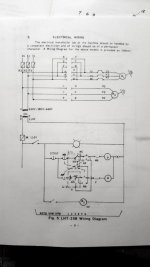
Original wiring schematic.

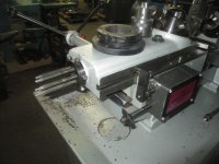
Threading fixture from a Valuemaster lht-25b (not my machine but principally the same)


This lathe has a threading feature that I would like to use. I have not used this lathe, or any turret lathe for that matter, so my information is from the manual and looking at the machine.
If I use incorrect terminology for the machine functions that’s why.
The lathe has two momentary contact switches for FORWARD and REVERSE as the turret is cycled through the threading station.
The vfd has what seems to be common to most vfds’, an ability to use a 3 wire interface or 2 wire via 7 logic inputs.
Logic is 24vdc with 100mA
Using the 2 wire logic inputs they require Maintained Contact switches for forward, reverse.
Using the 3 wire the stop is maintained and the start is momentary and forward/reverse maintained.
I can only use a 3 wire or a 2 wire not both.
The following is from an email conversation with an Hitachi tech (his reply italicized)
“I have three questions concerning switches to the intelligent inputs,
1. Can I use momentary switches or must they be constant contact type. If yes, is there a parameter change?
If you use the inputs as RUN forward and RUN reverse, they are maintained. If you use the inputs as START/STOP the stop is maintained and the start is momentary. Each input can be programed individually.
2. Can I use both a three wire configuration and the other logic inputs having a forward, reverse type inputs?
You must use either 2 wire or three wire configuration. You cannot use them at the same time.
3. I'm installing this on a turret lathe with an existing threading feature, this uses two switches. When in use when selecting the threading tool it contacts a switch causing the spindle to turn forward when a prescribed depth is reached it contacts another switch sending the spindle in reverse. Using this VFD can I go directly from a forward condition to a reverse condition without a stop command?
When the drive transitions from a RUN forward to RUN reverse, it will decelerate at the deceleration rate programmed in parameter F003, after reaching 0Hz, the drive will starting running in reverse.”
The problem is this, the threading contacts are momentary and the forward/reverse logic inputs on the vfd require the switch to be maintained with a STOP action between state changes. The vfd will stop if it receives both a forward and reverse input simultaneously.
So, I need a main control for forward and reverse and the threading switches for forward and reverse how do I achieve this with the vfd?
Original wiring schematic.

Threading fixture from a Valuemaster lht-25b (not my machine but principally the same)


