I am not sure if your warning is for safety concerns or for properly driving the motor.
AC Voltages are commonly, almost universally measured in RMS values. RMS stands for Root Mean Square which means you take a number of intervals over each cycle, square the value at each, average them (the Mean), and then take the square root. This is done with calculus so the effective number of samples over that cycle is infinite. Anyway, the RMS value is the effective DC equivalent value of that AC waveform in terms of power or heating effect.
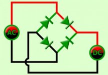
When you rectify an AC Voltage, you get what is called pulsating DC. If you use a full wave rectifier to get a positive Voltage, then the positive half cycles will be the same value after the rectifier as they were before it. And the negative half cycles will appear as additional, positive going half cycles between the original positive going ones. There will be no negative going half cycles. But, this pulsating DC waveform is still not a true, constant value DC: it goes from zero Volts to the maximum Voltage at a rate (frequency) that is twice the rate (frequency) of the original AC. Actually there will be a small Voltage drop in the rectifiers so the DC pulses will be a little lower than the original AC by that amount but this is frequently neglected at higher Voltage levels (115 V - 2 V = 113 V). Due to this pulsating nature of the pulsating DC, we need to use the same RMS value of that DC to find it's effective heating or power capability. Thus if we have a 115 VAC, which is a RMS value, input to the rectifier, we will have about a 113 VDC RMS value at it's output: virtually the same thing. And BOTH of these will have a PEAK value that is around 1..4 times the RMS value or around 160 Volts.
The point is this, a DC motor that is rated at 115 VDC will work with a constant DC Voltage of 115V. But it is the RMS value that counts here and motor ratings are always in RMS values. Since a constant DC Voltage will have the same peak and RMS values the RMS value of that 115 VDC will be exactly that or 115 VDC. Now the output of our full wave rectifier is also 115 V RMS so it will be exactly the same when running that 115 VDC motor as the constant 115 V DC Voltage was. They are exactly equivalent, neglecting the small loss in the rectifiers of course. So, if no filtering capacitors are used, then there is no need for any caution when powering a DC motor that is rated for 115 VDC with a DC Voltage that is derived by a full wave rectifier from the 115 VAC line.
On the other hand, if you were concerned with safety, there still is little need for additional caution. In fact, as the Edison vs. Westinghouse debate on DC vs AC, with equal (RMS) Voltage values, AC is actually more deadly than DC. So, more caution would be in order when working with an 115 VAC motor than when working with a 115 VDC motor that used filtered, non pulsating DC. The 115 V AC Voltage would have a significantly higher peak value than the constant DC would.
I would suggest that roughly equivalent safety precautions be taken with either one.
As one of my favorite authors* said, TINSSAAFL (There Is No Such Thing As A Free Lunch). When rectified DC is filtered, you do get a higher Voltage: about 1.4 times higher or about 160 Volts from a 115 VAC line before the rectifier. But, you do not get more power that way. In fact, due to circuit losses, the available DC power will be less. What happens is as you try to draw more and more current from that filtered 160 V supply, the capacitors will start to discharge after the peaks of the AC line and their Voltage level will drop. They will charge up again when the next half cycle comes along, but for part of the half cycle the actual Voltage will be less than that peak value of 160 V. So, you wind up in effect having a lower value of DC Voltage. Again, it will be the RMS value that counts. The more the current drawn, the lower the DC Voltage will drop between half cycles and hence, the lower the RMS value of that DC. How much it will drop will depend on the value of the filter capacitor(s). This could be self regulating if the filter capacitors are small or if they are larger, the AC current draw could increase to keep them charged to near the full value. This is where it would be possible to damage a DC motor with rectified AC. If you keep the value of the filter capacitors low, then this should not be a problem.
* Author reference = L. Ron Hubbard
Watch it with the bridge rectifier also. Rectifying 120VAC full bridged will give you quite a lot more than 115VDC depending on how you do it. Large enough smoothing capacitors will raise the effective voltage by 1.414x, producing about 170VDC. No capacitors will give you very uneven voltage but most motors don't mind this.


