What's new
What's new

Intersting problem with RPC starter

Froneck

Titanium
Joined
Dec 4, 2010
Location
McClure, PA 17059
The other day my RPC started as it always did. Was running fine then the contacter dropped out while I was away form the lathe, motor was simply idling and RPC running. Thinking there was a dip in the power, I restarted but it failed to lock on, did it a few times, contacter did lock but as I walked away it dropped out. My system is simple, I have 30Amp 4 pole relay connected to a 50Amp contacter. Push button for start operates the 30Amp relay (120VAC coil) it then energizes the 50AMP that connects the RPC motor to the line as well as all other motors wired parallel to the RPC motor. All machines in the shop are connected via contacter so when RPC contacter removes power from the machine line all contacters drop out so nothing is connected at start-up except the RPC motor. Having had problem with start-up in the past and when checking found the 30Amp relay probably from China was the cause. Being I didn't use all the contacts I moved to another set. Every time I had problems with starting it was always the 30Amp relay, the 50Amp being a good Square D never gave me problems. Thinking that the 30Amp was again the problem (not thinking) I searched my stash and found a 30Amp Schneider Electric. I replaced the Chinese relay, reconnected everything and gave it a test. Worked great better than before! Before when starting I could hear the relay/relays chatter before being locked. But now all I hear is a click! The start cap is connected to the 30Amp relay so when finger is removed from start button 30Amp relay drops out disconnecting the Cap. Was happy at the time thinking I finally got rid of that Chinese relay! Later thinking at what I did, the Chinese relay couldn't have been the problem. I'll know better today after it runs for 8 hours. Anyone have any ideas? Before as I mentioned the 50Amp would not lock up, RPC started but would not stay running when start button was released. However start button was only wired to 30Amp relay, contacts on the 30Amp became the start for the 50Amp that locked itself on.
 
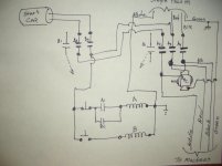
I'll make a drawing and take a photo of it. I'll try to get it here in readable size. However it's simple. The 50Amp contacter is wired as if 3 phase was available, single phase 240vac to only 2 of the 3 terminals. Since neutral is available as well as the ground in the 4 wire input, the neutral is connected to one side of the coils of the 2 relays. One of the 240VAC input is fed to both start and stop push buttons. The other side of the stop is connected to Aux. contacts NO, other side of the NO connected to the coil on the 50Amp relay. So when energized the 50Amp will lock it self thru the stop switch and Aux contacts. All outputs of the 50Amp contacter are wired to the RPC along will all machine wiring parallel. In addition the ground is also connected to all motor wires so it simply becomes like all 3 phase connections 3 hot lines and a ground no neutral. The start switch simply energizes the 30Amp relay. One set of contacts Parallels the NO contacts on the 50Amp to operate it when the 30Amp energizes. Simply it becomes the start switch for the 50Amp. The Cap is connected double pole, the other side one is connected to 240VAC and other to the 3rd contact of the 50Amp as if it was the 3rd line of 3 phase. So pushing start energizes 30Amp which them energizes the 50Amp and also connects the start cap. to the now closed contacts applying 240VAC and a phase shifted via start cap to the RPC and all other connected machines.
 
I'll make a drawing and take a photo of it. I'll try to get it here in readable size. However it's simple. The 50Amp contacter is wired as if 3 phase was available, single phase 240vac to only 2 of the 3 terminals. Since neutral is available as well as the ground in the 4 wire input, the neutral is connected to one side of the coils of the 2 relays. One of the 240VAC input is fed to both start and stop push buttons. The other side of the stop is connected to Aux. contacts NO, other side of the NO connected to the coil on the 50Amp relay. So when energized the 50Amp will lock it self thru the stop switch and Aux contacts. All outputs of the 50Amp contacter are wired to the RPC along will all machine wiring parallel. In addition the ground is also connected to all motor wires so it simply becomes like all 3 phase connections 3 hot lines and a ground no neutral. The start switch simply energizes the 30Amp relay. One set of contacts Parallels the NO contacts on the 50Amp to operate it when the 30Amp energizes. Simply it becomes the start switch for the 50Amp. The Cap is connected double pole, the other side one is connected to 240VAC and other to the 3rd contact of the 50Amp as if it was the 3rd line of 3 phase. So pushing start energizes 30Amp which them energizes the 50Amp and also connects the start cap. to the now closed contacts applying 240VAC and a phase shifted via start cap to the RPC and all other connected machines.

Do any of these machines have manual starters? And if so, is it possible you are trying to start them at the same time as starting the RPC?

Tom
 
All machines connected have contacters so NO other motors are attempted to be started. All wiring to the machines is identical, I can move any machine and connect via twist lock plug and rotation be correct in addition internal wiring is connected so that the "created" third phase is connected only to the Drive motor. No transformers, lights, coils, single phase coolant pump motors nor anything else uses the created phase. So when starting the RPC, only the RPC is started, then machine motors will be started via individual Start push button, when stop on RPC contacter is pushed all machine motor are stopped and will not self start.
Drawing is almost correct but 50Amp relay is 3 phase so has 3 contact M. Motor only is connected to output side (RPC side) Cap is connected to input side via double pole. Both sides of the Start Cap is connected to a NO contact one of the other side is connected to M1 3rd contact on the coil source side and the other to one of the input line side. As I mentioned the 50Amp contacter(M)is connected as if 3 phase was available and the phase shifted output is connected to the 3rd connection along with the 2 single phase. Locking NO switch is Aux. Contact. The Cap is connected to the 30Amp (A) on both sides (double pole connection) So shifted phase must go thru 3 contacts to get to the RPC. It's wired Line-NOa-Cap-N0a-NOm-RPC 3rd wire. No balance Cap, I don't like them! Line feeds machines with various HP from 1HP to 10HP.
 
Did you check the coil supply voltage? A chattering coil is a symptom of low coil voltage. It is unusual for a sealed in coil to dropout unless the voltage drops significantly, like down 35% or so.

Tom
 
All the coil voltages listed are 120VAC. At one time I did measure my 240VAC to Neutral and it was something like 124VAC. Thinking about the problem I had it seem to might have been the coil in the 50Amp but when not thinking and assuming the problem was with the Chinese 30Amp relay that did provide problems in the past when I did trouble shoot the issue. I simply replaced it with a quality relay and everything worked great. Now I get a simple click of the relays and RPC starts as if connected to 3 phase. I'm not sure if because the double pole connection on the Cap allows to to be disconnected charged, I know it must be discharged prior to working on the circuit, having nothing to discharge the Cap it will retain a rather substantial charge. No evidence of arching on the contacts, problem was previously the mechanism holding the contacts failed. One would think that when the 50Amp relay energized it's aux. contacts should have locked it up. Wiring was direct only thing was the stop switch in series with the coil. But if it was the problem changing the relay would not have changed anything! Only other possibility I can think of is the contacts on the Chinese 30Amp relay didn't quite mate and voltage was low on the coil and it didn't have enough to close the aux. contacts. Today it ran for hours with out problems and as I said relay operate with a solid click! Motor starts as if connected to 3 phase. All that was changed was the 30Amp relay that was new when installed and gave problems from day 1! Only reason I used it was that I had it and it was well over rated for the use I intended.
 
I think there is a gremlin you haven't found yet. Once the 50 amp seals in, there should be no reason for it to drop out other than loss of coil power. The only function of the Chinese switch is to get the motor running and seal in the 50 amp. After that, it can go to a bar and have a few. The chattering of the thirty amp, even a poorly designed device, is symptomatic of low coil voltage. I have tested hundreds of switches for pickup and dropout, and in virtually all cases the device would close cleanly at 100% voltage. By NEMA standards all devices need to operate properly at 85% and 110% of rated voltage, which means that the actual pickup voltage needs to be around 70-75% voltage. I wont go into the details, but the chatter is due to a miss match of the magnet pull curve and the spring load curve at kiss.

Tom
 
I have no idea what the problem was! My rush to judgement saved the day. Then after thinking about the problem I couldn't figure why changing the 30Amp relay helped. But in the past when anything failed it was the 30Amp Chinese relay that was new when installed. The 50Amp as an old Square D. Every thing is working great, actually better than it ever did! RPC starts so fast I don't have to hold the start button to keep the start Cap connected. Might have something to do with the double pole connection. Only issue is that Cap has to be discharged before working on it as it remains well charged long after power is removed.
 
Only issue is that Cap has to be discharged before working on it as it remains well charged long after power is removed.

Connect a resistor across the capacitor. The value in ohms and the size in watts should be chosen so that the discharge time is not too long, or too short. I would chose a discharge time between 30sec to 1 minute.

You changed out the relay and things worked. Pay attention to the connections, especially the screw down type. A few times I had misbehaving electrics and found loose connections.

Drawing of the whole thing?
 
Schematic

Connect a resistor across the capacitor. The value in ohms and the size in watts should be chosen so that the discharge time is not too long, or too short. I would chose a discharge time between 30sec to 1 minute.

You changed out the relay and things worked. Pay attention to the connections, especially the screw down type. A few times I had misbehaving electrics and found loose connections.

Drawing of the whole thing?

When I disconnected all stranded wire had tight stake on forks and tight screws, nothing even slightly loose. No solid wire used.
I don't want to add a resistor, when my RPC starts it's as connected to 3 phase. The start button was done that way so as to allow me to be the timer, push and hold until RPC was up to speed,usually 3 seconds. Now it's push and let go, heck I think the RPC motor is up to speed before I let go, maybe 1/2 second, 1 second at the most! However I am using a Delta wound motor with 1200 RPM Sync. Speed.CIMG1900.jpg
 

Attachments

  • CIMG1901.jpg
    CIMG1901.jpg
    66.8 KB · Views: 47
Last edited:
You can add a 20k - 100k resistor across the capacitor terminals. It will have no effect on the circuit except to discharge the start capacitor. The fraction of a second that it is in the circuit (when B relay closes and then opens) is of no concern.
 
Your diagram and mine are fundamentally the same. You don't need to route the start cap through the main contactor A2 or start contactor B2. You are just adding an additional joints that can cause problems. My guess is that the Chinese switch is defective and that it was chattering and not making a good connection of the capacitor. This goes back to the reliability will go down with additional contacts. If you want, send me the contactor and I will tell you what's wrong. Otherwise just enjoy a trouble free starter.

Tom
 
One thing I avoid is high voltage controls like that, especially when the switches are on a panel swing out door. I tend to use 24Vac. Anyway, be careful.
 
One thing I avoid is high voltage controls like that, especially when the switches are on a panel swing out door. I tend to use 24Vac. Anyway, be careful.

Not saying that what you do is wrong, only that it has been common practice to use 120 volt control on doors for as long as I know. Actually, NEMA standards used to be that a minimum of 120 volts would be used in control circuits. The reason was that anything less could produce fidelity failures. Since then special control devices have been developed to work with the low voltages used with computer based devices.

Tom
 
No Doors, box cover is attached with 4 screws. 120VAC coils because that's what was available in my junk pile/stash. RPC starting was not an issue nor has it ever been. Issue that required my attention was the output contacter would not lock-up. As I said my rush to judgement had me replace the Chinese contacter but it should have not been the problem and I realized that later but replacing the Chinese contacter fixed the problem. All is working better than it did before!
Yes Tom the schematic is virtually the same but I was asked to supply it.


Back
Top