What's new
What's new

Inverter VFD VSD issue I'm getting 122vac on PE terminal?

alastairseggie

Aluminum
Joined
Jun 26, 2013
Location
UK
Hi all,

I'm looking for a bit of guidance here from those in the know.

I have a single phase to three phase 3kw inverter. When I plugged it in to the mains 244VAC 50Hz (UK) the RCD tripped instantly this is before starting the drive. Connecting the motor makes no difference.

On investigation I am getting exactly half the input voltage 122VAC 50Hz between Live (or Neutral) and the Protective Earth circuit. This again does not change with motor connected or not or drive running or not.

Apart from this obvious safety issue the drive seems to perform fine!

My question to all the VSD gurus is what/where should I be looking for the issue? I know enough to know that this is likely to be in the rectification of the 244VAC but where why would it end up on the PE? Rectifier shorting to the heat sink?
Coupling Capacitor shorted to earth.... not sure why it would be coupled to earth rather than to neutral.

Basically I am stumped and don't have enough knowledge to narrow down the fault finding process.

Finally I know that RCD's give issues with inverter drives but my understanding is that this is due to harmonics or induced currents when the drive is running and to me does not seem to be my issue.

Any theory or assistance is very welcome.

Al
 
Last edited:
1) do you have the PE wire connected? (I'm thinking not)

2) I assume the motor runs OK?

3) If PE is not connected, I assume you have measured with a high impedance multimeter, such as a Fluke or whatever standard brand you have over there.

May I suggest you try connecting the PE if you have not? If you like, you can start off by connecting it through a standard low wattage lightbulb, if you still have any.

My thought is that you are seeing the effect of whatever the VFD has for an EMI filter. Basically leakage current.
 
Hi JST,

1) do you have the PE wire connected? (I'm thinking not)
Originally I had it connected but it trips the RCD instantly. So I've tested with out it and the VSD appears to work well.... On the very basic settings I've managed to programme.

2) I assume the motor runs OK?
Yep fine
3) If PE is not connected, I assume you have measured with a high impedance multimeter, such as a Fluke or whatever standard brand you have over there.
Exactly. Voltage between PE and live is 122vac exactly half the mains. Putting the multimeter in to mA it blows the 800ma internal fuse.


May I suggest you try connecting the PE if you have not? If you like, you can start off by connecting it through a standard low wattage lightbulb, if you still have any.
What like a 20watt 250vac incandescent bulb.....? What does this do? limit the current flowing back to the earth and RCD?


"My thought is that you are seeing the effect of whatever the VFD has for an EMI filter. Basically leakage current.

I think you are right on the money here voltage wise , I've seen the same on the other VSDs I have but where it differs is that there is current too and that is what is tripping the RCD. There are 2 Y2 47nf polypropylene filter caps one from live to the PE and the other from neutral. I suspect one of those is bad and is allowing current to flow. Just a theory for now.

Thanks for the help
Alastair
 
Eh.... If you blow an 800 mA fuse, there is more than just leakage going on.

I'd bet that light bulb would light..... yes, the idea was a load to see if the voltage dropped with a load.... If it's leakage, it will drop like a stone as soon as the load is on it. Evidently it did not.

What brand of VFD is it? What model?

>>>>>>>>>>>>>>>>>>>>>>>I'd not use that until this is sorted out. <<<<<<<<<<<<<<<<<<<<<<<

I was OK until you mentioned the 800 mA fuse. THAT I do not like.

Take a good look over your wiring inside, and be certain there is no loose strand of wire touching things it should not be.

next, disconnect the VFD from everything, and measure resistance from mains and motor terminals to the PE terminal. All 6 lines, L1, L2, L3 and U, V, W. Report back what you find.
 
JST & Mitch

Thanks for your replies this is really helping. OK I think I may have caused some confusion here so let me talk you through exactly what I did. Also I need to say I Commission VFD's all the time at work. I don't install them, that is done by an electrician ( I am a chemical engineer) he does all the electrical checks I set up the parameters and how it will operate. If I have an electrical issue I go to the electrician. All of that said I over the years I have come to know how they should be wired and what the correct (according to the Manufacturer) way of bonding and EMI precautions to be taken.

The VFD is a Siemens Micromaster Vector. I bought it on ebay see here Siemens Micromaster Vector Inverter Motor Drive Converter Single Phase to 3 | eBay

Ok so here is a bit of a blow by blow of what I have done so far.

  1. I connected L + N + PE to reform capacitors as per manufacturers literature. The moment I connected the plug that instantly tripped the RCD.
  2. I then disconnected the earth and tested the voltage between PE and L and the PE and N this gave me 122VAC. Resistance between PE and L or N was in the Mohms some thing like 9Mohm I cant remember exactly what it was.
  3. I then reformed the caps over night with out the PE connected just L + N. I thought this might be a capacitor leaking and that the reforming might sort it out.
  4. Next morning I tried measuring the voltage between L + N and the PE and it was still 122VAC....Bugger.
  5. I decided to try the drive as it all seemed to be working, all except the tripping the RCD that is. Note: up to this point I had never started the drive just put power on to the terminals. I temporarily connected it to a 1kw motor, input the motor specs and spun for direction... all was well. Next I ramped it up to 50Hz and down again all worked fine. I then disconnected the motor and I have not re connected the motor since then.
  6. At this point I thought that it might just be the the way the VSD worked and that it would not work on a standard RCD. The Manual says a type B RCD is needed I have a standard 30mA RCD. However I was worried about how much current was being output but the PE. I did not want to put this on the other NON RCD circuit without understanding how much current I was sinking back to the mains earth. So I decided to have a look at my other VFD's and found that they also had a high Potential on the PE if the mains earth was not connected. These VFD's did not trip the RCD so I tried to measure the Current between the PE and the mains earth and as JST suggested the voltage disappeared and there was no current flow. Well none that the Multimeter could detect. Note: that these two VFD's are all running well.
  7. Next I decided to measure the current flow on this VFD between the PE terminal and the mains earth. I put the Multimeter to mA and tested. This is when I blew the 800mA fast blow fuse. At this point I realized that although the VFD was operating correctly it was in an unsafe condition. This VFD came from an industrial setup and I think that if this was in an industrial non RCD protected setup this fault may not have been detected and the current would simply go to earth.
  8. I had a look at some old circuits Diagrams I used to use for making PSU's, than and a bit of google....and I have begun to suspect that the filter caps that go between L and PE and N and PE. I have had these go bad on me in the past and the cap tests fine except for its ESR and it gives a similar result i.e. 1/2 the input voltage as an AC voltage.

I need to speak to the seller now before I try to undertake a repair as I should have been getting a 3kw drive but only got a 2.2kw one so we need to sort that out before I go doing board level repairs.

Does anyone agree/disagree with my possible diagnosis of the filter caps?

Alastair
 
Not really. But sort of.

There is no way the caps SHOULD be connected like that. That would be against pretty much every "agency" approval I can think of.

Now, they MIGHT be connected that way, if for instance one of the capacitors has defective outer insulation, so that the clamp/holder is contacting the capacitor case directly. I'm not sure that would give you the precise AC reading, though. It might. It will be off-ground for sure.

A common connection is to use two seriesed lower voltage capacitors.... so the negative of one capacitor is at about half the DC volts. The negative "plate" must always be considered to be possibly touching the case, although usually there is internal insulation against a direct metallic connection. But the electrolyte connects everything.

A problem in the input protection is another possibility.... It's possible that certain types of failure in the input MOV protection (transient suppressors that protect against "spikes") could do what you say also. Maybe that "taken out of service" unit got a good zap at some point and an MOV failed.

A problem in any internal EMI filter might do that, although it would depend a lot on what sort of filter, if any, is present.

We just had a similar situation at work.... A VFD that goes overcurrent if the ground is connected, but appears to have no measurable fault.

Bottom line is that you don't need to do a lot of diagnosis.....

The proper response, if you are certain your own wiring is good, is "Ugh.... VFD bad, give me new one". Hitting the unit with your large stone club is optional.
 
Alastair-

It sounds like your VFD might have a built-in filter. Filters can cause RCDs to trip, particularly domestic RCDs, which are set for lower currents than industrial usage. Typical industrial VFD filters do leak a little current to earth on power-up. When I have bought VFDs recently I have specifically checked this for this problem and only bought VFDs and filters that are intended specifically for the domestic environment for my garage usage. Your level of leakage does sound a little high, so this may not be the sole or only problem, but worth consideration.

Is this for your S&B 1024? If so I have had success with my VFD conversion and if you want to compare notes, just send me a message.
 
It sounds like your VFD might have a built-in filter. Filters can cause RCDs to trip, particularly domestic RCDs, which are set for lower currents than industrial usage. Typical industrial VFD filters do leak a little current to earth on power-up. When I have bought VFDs recently

Your level of leakage does sound a little high, so this may not be the sole or only problem, but worth consideration.


800 mA is "a little high" all right..... that would light up a 60W lamp!

Exactly. Voltage between PE and live is 122vac exactly half the mains. Putting the multimeter in to mA it blows the 800ma internal fuse.
 
Hi, Billmac

You may be right, the manual says to use a type B RCD so I might try to get one of those.

I have had some time in the garage now and I have discovered that there are 3 capacitors that are between earth and various other items
  1. live to earth - 47nf Y2 Polypropylene MKP capacitor
  2. neutral to earth - 47nf Y2 Polypropylene MKP capacitor
  3. rectifier output to earth - 220nf X1 Polypropylene MKP capacitor

I have to disconnect them all to not get a RCD trip. well that is not exactly true I have to disconnect the cap between rectifier and earth. and then the cap that is between live and earth. the one on neutral is fine left in ( I have tried swapping caps and which side i put live into). I replaced the 220nf cap with a new one and the same happens so I am no longer sure that it is the caps.

JST - what am I looking for EMI filter wise can you describe what the package would look like? and where I am likely to find it.

Alastair
 
First, there isn't a one of those capacitors that should allow 800mA of current to flow, IF it's good, without the inverter being on and switching.

So if the 800 mA fuse blew with just power applied, with the VFD on standby, one of those must be bad.

When the unit is switching, there will be more current flow, since there will be some higher frequency components. Those go through capacitors more readily than 50 Hz. I still don't think anything near to 800 mA will flow, even then.

Filter? You mean in the unit? You may have found half of it.... There may also be a 3 phase common mode choke, that will be a toroid core with three separate windings on it.
 
Hi, Billmac

You may be right, the manual says to use a type B RCD so I might try to get one of those.
......
JST - what am I looking for EMI filter wise can you describe what the package would look like? and where I am likely to find it.

Alastair

Alastair,

I would try to avoid fitting an industrial rated RCD in a domestic garage. It doesn't give you as much protection as the normal domestic rated version, and you will typically be using hand tools and other equipment in a situation where that protection could be valuable.

I agree with JST that the unknown (but higher than 800mA) current leakage is more than just leakage through a filter, although the filter may be contributing. I do know from personal experience that industrial VFDs with filters can cause UK domestic RCDs to trip, even when there is absolutely nothing wrong with them.

The reason I think that your VFD may possibly contain a filter is that some now do and looking at the manual for the Micromaster, Section 9 seems to indicate that some models may have this, whilst others will use an external filter. I suggest you match up your VFD code with the tables to check exactly what you have got.
 
Bill,

The Drive is a 230V single phase Micromaster Vector. The Order No is 21-0BC40 so that makes it an Inverter Model MMV220.
The manual in section 8 page 65 states, "All 1 AC 230 V MICROMASTER Vector include integrated Class A filters. Optional external Class B filters are available (see section 9.3)."

WRT the safety side I would only use a type B RCBO to supply the drive and it is my understanding that the Type B offers more protection not less.....have i got that wrong?

alastair
 
I am not sure if I am reading all this right.
As far as I know, there should not be a "neutral" going to the drive. There should be 220 to L1 & L2 and nothing on L3 and (safety) "ground" on PE. From the drive you should have connection to T1, T2&T3 to the motor.
In the panel, "neutral" is the reference side for 120v operation.

I think things here in the UK are a little different ..... Well on the single phase domestic side any way. The AC lines are referred to as live and neutral and then you have earth.

Live and neutral are taken between 2 phases . This neutral is not the same as 3phases and a neutral.

Alastair
 
I am not sure if I am reading all this right.
As far as I know, there should not be a "neutral" going to the drive. There should be 220 to L1 & L2 and nothing on L3 and (safety) "ground" on PE. From the drive you should have connection to T1, T2&T3 to the motor.
In the panel, "neutral" is the reference side for 120v operation.

There are some very big differences between UK and US codes, electricity supply and wiring practices. For a UK 230V single phase to 3 phase inverter you connect the supply Live (L), Neutral (N), and Earth (E) to the inverter input.

Alastair - see this for good UK relevant background on RCDs
http://www.select.org.uk/downloads/BEAMA Installation RCD Handbook V2 2010 updated (2).pdf
 
Bill,

From what I can see type B offers all that Type a.c. and A offer and also offers smooth DC protection. So it actually provides more protection unless I am missing something. see this excerpt.

6.1.4 Types a.c.,A and B RCDs.
Residual current devices may also be classified as Type a.c.,Type A and Type B as follows:
Type a.c. Ensures tripping for residual a.c. currents, whether suddenly applied
or slowly rising.
Type A Ensures tripping for residual a.c. currents and pulsating d.c. currents,
whether suddenly applied or slowly rising.
Type B Ensures tripping for residual a.c. currents, pulsating d.c. currents and
smooth d.c. currents, whether suddenly applied or slowly rising.
For most applications Type a.c. devices are the most suitable. For special applications, refer
to the manufacturer.

Alastair
 
JST,

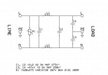
This shows almost exactly the type of filtering I have in the VFD.

http://www.schurterinc.com/content/download/339606/11198618/file/EMC+for+Dummies_+Final.pdf

This shows you the type of filtering I have.

I also knocked up a schematic of exactly what I have in the VFD
VFD Filter.jpg

There is also an inductor between the PE and the Heat sink and 3 other Capacitors. A 220nf between the DC negative and the PE. A ceramic 4n7 also between the DC negative and the PE and a ceramic 4n7 also between the DC positive and the PE. The smaller ceramics don't seem to be causing any issues. I am still unsure of the Inductor but as it is just a coil of thick copper wire wth out any ferrite there is not much that could be wrong.

Alastair
 
Alastair -

You can get RCDs with several different sensitivities in each type. I'm no expert but I think the norm for domestic and industrial usages require different sensitivities. See page 26 of the BEAMA reference.
 
yeah, that looks right. And yes, your common mode choke would have TWO windings, 'cuz you have a single phase input unit. I think I mentioned 3......

yes, the two caps across line to PE would give half voltage to the PE terminal if it's floating. But they definitely should NOT pass any heavy current like 800 mA.

The inductor to heatsink is to ground it for DC and 50 Hz, but "discourage" conduction of the high frequency "junk" switching signals that get capacitively coupled to the heatsink from the IGBTs.

Did you ever measure (with it disconnected) resistance from L1 and N to PE? Or from U, V, and W to PE?


Back
Top