What's new
What's new

Messed up my WNY RPC while moving

shandit66

Aluminum
Joined
Jan 5, 2011
Location
Toronto
I recently sold my old shop, stripped out everything and moved into my new garage. Unfortunately, I was very short on time while packing up the old shop and I didn't document things as well as I should have. Nor apparently pack them well


Its a WNY panel, version RP10.
So 10 hp planel, 230 v with a 5 hp idler, servicing a 5 hp lathe motor. \\
(I previously had a 10 hp idler on there, but thats all still in storage)

There were 4 caps:
- 2 black - Packard PRMJ270 start caps, 330 vac, 270-324 MFD
- 2 silver - I can't read the specs but assume they are the run caps

Last weekend I tried to install and hook up the RPC. But:
- the idler motor won't spin up to speed.
Its a 5 hp motor, thats blowing a 30 amp circuit, with no load.
(I checked the motor and its set for 230v not 460)

The start caps came loose, so did the wires. So I don't know how to hoop it back up.

This is my current state.
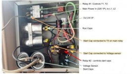
Phase Converter.jpg

I've not been able to find a wiring diagram for this.
I doubt anything is wrong with the unit, I likely just need to know how to wire up the start caps.

Any and all help is much appreciated!

Olaf
 
Looks like the start caps are supposed to be connected through the lower contactor that is controlled by the potential relay. One pole of that contactor should be between incoming mains (probably after the main contactor) and the start capacitor bank. The other pole should be between the other side of the start capacitor bank and the motor's generated leg. The generated leg must also connect to the potential relay (or voltage sensor).

It *might* also be designed for the potential relay to stay on the capacitor side of the contactor rather than the motor side, but I can't say for sure.

The picture came through as very low resolution and I can't make out enough detail to see exactly what you have going on, but the start cap wiring looks wrong.

I think you are on the right track, but I'm not 100% understanding your terminology. Appologies for my lack of proper electrical knowledge.

I've attached a link to image which will hopefully be larger

Public - Google Drive
 

Attachments

  • RPC2.jpg
    RPC2.jpg
    20.8 KB · Views: 36
Idler won’t spin up without the start cap hitting the 3rd leg.
Make sure you got 120v to line A and B at the idler. If you do but the motor won’t spin then make sure your getting start cap voltage on line C(3rd leg).

If both a and b are hot, then line c must not be or it’ll fire up.

Make sure you got 240v between line A and B at the idler.

You could have only a single 120v split phase wired to both line A and B! Make sure it’s 240v across and your start cap is hitting the 3rd leg
 
I'm not seeing anything too majorly wrong.

With power off and the capacitors discharged, disconnect the wire that the blue "voltage sensor" arrow points to on the voltage sensor (typically known as a potential relay). Then check for continuity between the now exposed terminal and the bottom right terminal that has the black wire snaking up to the main contactor.

If it is open circuit, then your voltage sensor is bad or miswired. If it is closed circuit, then that is not currently the issue, and you should check for voltage across the coil of "relay #2", which is the top most and bottom most terminal near the base. (It's a good idea to wire these to a meter *before* applying any power).


Of course before any of that you should check for incoming power as blob mentioned.

In my experience potential relay starting setups like this tend to have issues where the start capacitors won't cut out when the motor isn't up to speed.
 
WAIT A MINUTE!

Are those capacitors connected across L1 and L2? That won't do anything but buzz angrily. Tell me where the wire from the right side of relay #2 connects to.

I feel as if the white wire should actually connect to your 3 phase output. Possibly at the top most lug on the run capacitors.

A1 - The caps are not across L1 & L2
The black from the run caps goes to the left side (switched?) side of relay #2
The white goes now goes to start cap, which is wired to output B - the generated leg,
where L1 -> T3 -> C
and L2 -> T2 -> A

It looks like T2 -> the right side of relay #2, so I assume that the left is switched


Diagnostic Steps

1 - turn power on -
Across L1 & L2 = 239v
Across T2 & T3 = 0v
Across T3 & T1 = 118v same for T2 & T1

Relay #2 = 0v everywhere

2 - press the button
Across T2 & T3 = 216V - not sure why there is a voltage drop, but I doubt thats the main issue
Across T3 & T1 = 216v same for T2 & T1
Relay #2 - no power at all

Alright, well, it's looking like something is off with your potential relay
 
I hooked up another motor - thinking maybe it was the issue. Same symptoms.

Tried "pull starting" the motor - getting it spinning, then flippinng the switch.
No luck. it just jittered back and forth, almost like the phases were fighting each other and not coordinated

Wild ass guess, could the start caps be out of phase with the run caps?
 
You could check that the start and run caps connect between the generated leg and the same motor leg.


I would try putting in a button across the the voltage sensor to briefly energize relay#2 for startup.


Back
Top