So I promised I would do the write up for the 208/230 volt units on Friday. Well it's 2am on Saturday so it's close enough :-) I didn't have time to get it done before I went to work. I have attached some pictures for reference. This conversion requires about half the steps that the other conversion requires so a little less leg work is required but we still have to thank Dave Kamp because without his guidance I would have never figured this out.
First and foremost: This is a write up of what I performed on my machine that was successful. I am not responsible for anything negative that may happen to you, your property, your dog, the neighbors dog, neighbors cat, neighbors bird,....well you get the idea.
What I did from the start:
1: gain access - you will want to take both side panels off the unit.
2: break apart the coils. I un-bolted the red board where all of the wire connect, took all the wires off and sat them aside. (I did this long ago and ended up losing them but I meant to re-use them. Keep them till you are done because I wish I wouldn't have lost them.) Each coil will have 3 connections to it. one of each will go to one of the others with a crimped on connector. I cut them off to break the 3 coils apart. There is one terminal that goes on the back side of the red board that has 2 wires going into it. leave this together just don't connect anything to it. you are going to use the one side of the coil that connect to another coil and the other ring terminal that has only one wire crimped into it. this is 1 and 3 on the wiring diagram.
3: run line voltage wires to the "off" side of the power switch as shown in the wiring diagram. (hint: do not have them energized) I put the neutral in the middle of the 110 volt lines but placement doesn't really matter so long as you match what you want on both sides of the switch. (hopefully that makes sense)
4: Connect one of the 110 lines on the "on" side of the switch to one of the terminals on either the bottom OR the top coil.
5: Connect the other 110 line on the "on" side of the switch to the other coil (bottom or top) but the opposite side of what you did on the other coil (ex: so if on instruction #4, you connected the 110volt line to ring terminal on the top coil then on this step connect the 110volt line to the side of the coil that you disconnected from the others.) Now connect a wire between the 2 coils so they are wired in series.
6: at this point in time I was curious so I made sure nothing was at risk of short circuiting and i plugged it in and turned it on. (from afar of course) and BANG!!!......Just kidding. The welder made a fairly nice kinda steady humm. so i turned it all off and unplugged it and inverted my connections on one of the coils and tried again. This time the coils sounded like they were fighting each other so i turned it off and put it back the way I had it. So basically what i"m saying is, it might be a good idea to make sure you are off to a good start before you go any further, if you are following this to do to your own machine.
7: now came time to add the middle coil. The middle coil will utilize the neutral line that has not been used yet. On my machine, the middle coil shares the 110 volt line with the top coil. There was no reasoning behind this besides thats just which one I chose to share it with. It likely could be shared with either one. The other side of this coil connects to neutral. BUT! in addition to this you are going to have to put capacitors in between the coil and the 110 volt line to perform the phase shift similar to how it is done on the original conversion. On my unit I have the capacitors only on the 110 volt line for the middle coil and NOT the neutral line. I had bought 2 capacitors for the conversion before I dove into it and realized that what I had was different than was was in the conversion. But it worked out because I ended up needing them both. I tried with just one at first and it had a decent humm to it, not great but it didn't sound like it was fighting itself. I added the other in series to the first and it sounded pretty damn good. If I had another laying around I would add it to see if it sounded even better but where it is right now is very very pleasing to me. (side note: You may want to try inverting your connections to this coil to get the electricity flowing in the correct figure 8 pattern. just listen for the different humms. they will be distinct and you will know. ) I believe I have 63 micro fared run capacitors. (2 of them in series). I do not know if a single 126 micro fared capacitor would produce the same results or not. I don't know why it wouldn't but someone smarter than me (Dave Kamp) might be able to answer that. I also was too lazy (excited to get it up and going) to put the resistors on the capacitors to bleed them down. I don't know if that would make a difference in performance either, but I will tell you this. Those capacitors will hold a charge for a L O N G time. (wink wink wink wink) (DON"T TOUCH THEM if you are lazy,...err excited like me) (end wink)
8: Side notes. The fan can obviously just be connected one side of the fan to one of the 110 volt lines and the other side of the fan to the other.
The 110 volt plug on the front of the unit, I connected to one of the 110 volt wires on the "on" side of the switch and the neutral on the "on" side of the switch because I wasn't sure if the transformer that controls this would put out the correct voltage and knew that I could get the correct voltage this way.
9: The secondary side of the coils that is converted to WYE in the original conversion does not need to be performed. I had done this in the early stages of my conversion and experienced erratic performance from the welder. There was almost no low head control and it was almost impossible to weld thin metals with it. I converted it back to delta under the instruction and explanation of it not needing to be converted from Dave. ( see earlier posts if you are curious)
Ok so thats about it besides putting panels back on and insulating everything. The left side panel (looking at the unit from the front) I only removed so i could get easier access to the 110 volt plug wires on the front of the unit. I also cleaned the brushed and lubricated the screw and chains that move the sliding doohickeys on the coils.
first picture is the wiring diagram I cobbled together.
http://www.practicalmachinist.com/v...ccessful-cp-200-conversions-208_230-cp200.jpg

second is showing the top coil (side that was disconnected from others)
http://www.practicalmachinist.com/v...cp-200-conversions-img_20141224_202334205.jpg

third is showing the connection between the top and bottom coil.
http://www.practicalmachinist.com/v...cp-200-conversions-img_20141224_202405340.jpg
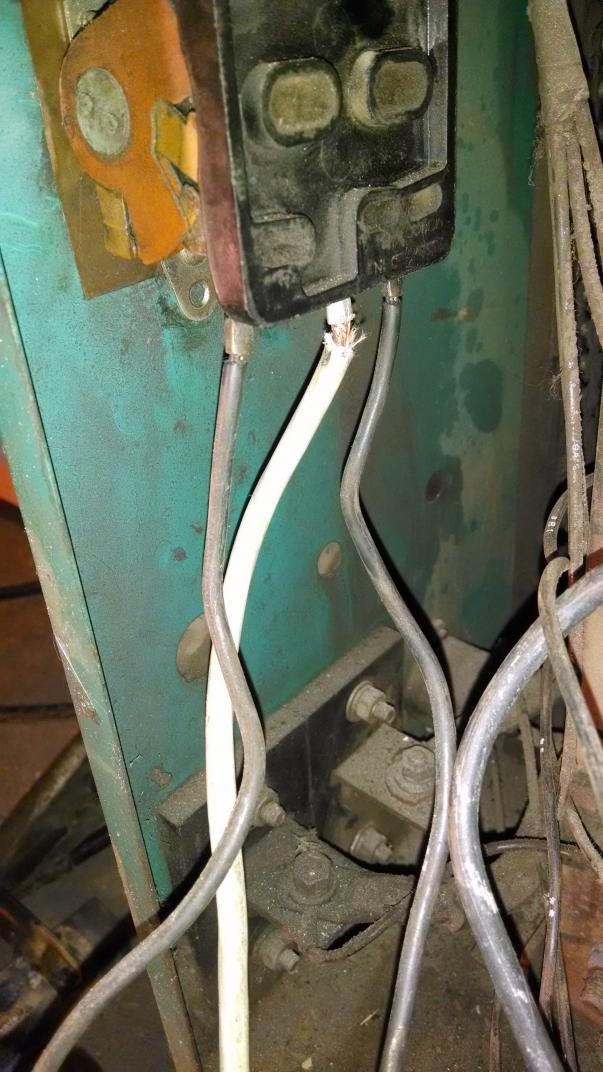
the fourth is showing one of the connections for the middle coil.
http://www.practicalmachinist.com/v...cp-200-conversions-img_20141224_202422483.jpg
The fifth is showing and overview of the whole unit.
http://www.practicalmachinist.com/v...cp-200-conversions-img_20141224_202435857.jpg
I will make a post with a few more pictures right after this post since I can only post 5 pictures at a time.