What's new
What's new

Miller FC-600 Single Phase Conversion Help

zachoak

Plastic
Joined
Oct 23, 2020
Hello!
I just got done finishing the Haas Kamp conversion on 2 of my CP-200s. I got a deal on an FC-600 that I couldn't pass up. I have been working on creating a new schamatic for the conversion and was wondering if anybody could double check my work.

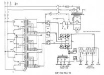
Here is the original schematic
FC-600 Original Schematic.jpg

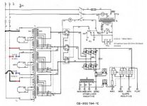
Here is the new schematic after removing and adding connections
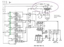
FC-600 Single Phase Conversion.jpg

1.) I was wondering if I need to get rid of the jumper in the green box? I have looked at quite a few of Dave's guides, but he leaves it in sometimes and sometimes he takes it out. I assume that it needs to be taken out, but how do I know?

2.) In the purple oval, do I need to rewire anything over there? I don't think I should have to because it was only using two lines to begin with

3.) I was also wondering what range of capacitance I should be using. I used Haas' capacitance formula to get 300uf total (or 150uf split between banks). Should I expect the welder to operate within a range of about 120uf-180uf, or should I keep the tolerance much tighter?

Any help would be greatly appreciated. If you need pictures or anything else, Ill try to get back to you as soon as possible. I'm trying to make the pictures bigger, if I can figure it out I will change them
 
Last edited:
I'm pretty sure that I have worked it out. The machine appears to actually be configured in wye because of the single line connection to all the transformers. This should mean that it can be converted similar to the CP series welders. I should be using the 460 taps instead of the 230. A̶ ̶c̶o̶n̶t̶a̶c̶t̶o̶r̶ ̶m̶o̶d̶ ̶m̶a̶y̶ ̶b̶e̶ ̶n̶e̶c̶e̶s̶s̶a̶r̶y̶ ̶f̶o̶r̶ ̶i̶t̶ ̶t̶o̶ ̶w̶o̶r̶k̶ ̶p̶r̶o̶p̶e̶r̶l̶y̶,̶ ̶b̶u̶t̶ ̶w̶e̶'̶l̶l̶ ̶s̶e̶e̶. If anyone sees something wrong, please let me know. Ill be trying it out when I get the time and parts to do it.

Here is the new schematic I have made
FC-600 Single Phase Conversion V2.jpg

****I labeled capacitors as 150uf, but it actually needs 300uf per bank. I misunderstood what I was reading****

****UPDATE**** The contactor mod will not be applicable. The contactor is labeled as W - I was under the impression it was SR1. Since this is before the transformers, adding a bar would make the machine impossible to run as nothing would be connected. Some wires would have to be spliced together before the thermostats to get the desired output. More Info Further Down

The conversion should go something like this:

1.)Labeling Terminals

Trace wire 8, Label it as Terminal #1 and sequentially 1-12 on the way up or down
2.) Back Panel (Removing Connections)

Cut and Remove jumper wire connecting terminal #4 to #8
Cut and Remove jumper wire connecting terminal #8 to #12
Cut and tape wire #7 at terminal #9 (this is the unused power wire)
Cut wire #9 at terminal number #4 (this will be installed on terminal #4 in the front)
*Fan wire does not need to be removed as it is in a different part of the circuit. Unlike the CP series welders where the fan is with the main transformers*
3.) Front Panel

Install a red jumper from terminal #4 to terminal #9
Install a black jumper from terminal #1 to terminal #12
Crimp ring lug to wire #9 and wrap in red tape. Connect to terminal #4
Connect black wire (for cap bank) to terminal #1 and a blue wire to terminal #5
Hook up first set of caps
Connect red wire (for cap bank) to terminal #4 and a blue wire to terminal #8
Hook up second set of caps

4̶.̶)̶ ̶C̶o̶n̶t̶a̶c̶t̶o̶r̶ ̶
S̶e̶t̶ ̶u̶p̶ ̶c̶o̶n̶t̶a̶c̶t̶o̶r̶ ̶b̶a̶r̶ ̶i̶f̶ ̶n̶e̶c̶e̶s̶s̶a̶r̶y̶

4.) Possible rewiring between secondary coils and thermostats
Some wires would have to be spliced together before the thermostats to get the desired output. This should be able to be done by connecting lines 48,44, and 54 together, and removing the connections that tie the wrong sections of the coils together

Here is a very oversimplified version of the schematic if that helps people. You may notice that it is pretty much exactly the same as the CP series conversion
Oversimplified Convert.jpg
 
Last edited:
I was wondering if this would be converting my primary side to delta with this schematic?

This would involve deleting the jumpers from terminal 4 to terminal 8 and terminal 8 to terminal 12. Then you would install a jumper from terminal 4 to terminal 9. I got this idea from Dave's DeltaWeld 450 single phase conversion found here Miller deltaweld 450 converted to single phase

Here is the Schematic that I believe would convert it to delta on the primary, which should eliminate the need for converting the secondary side to wye
(Possibly Delta)FC-600 Single Phase Conversion.jpg

I've also updated the schematic for the wye primary side. I mixed up some wiring colors and switched the capacitor connections around
FC-600 Single Phase Conversion V2.jpg\

Also, I never expect to use this machine at its fully rated power (which is at about 81 amps). Should I expect only 40.5 amps at half the welders power of 300 amps, or this not how these machines work.
 
Hi Zach!

Yeah, so this is a 230/460 WYE input. When you rewire it, you'll be setting the transformer windings to series, configuring them for 277 from centerpoint to lines, which once broken out separately means you'll be feeding 240v single phase into each 277v coilset. Just like the CP-200, there will be a corresponding drop in secondary voltage.

Converting the tail-end to Y might be necessary to bring that back up... BUT... i wouldn't bother delving into that until you've had a chance to try it AS IS. The CP responded to it substantially, but this beastie might not need it in order to be a good steel-burning machine.

Considering the heft of that machine, I would start smaller on the capacitor sizing, and once it's running, work your way up. There's lots of iron in that machine's core, it will not take much for it to circulate, and frankly, I suspect you'll run out of power service TO it, before it finds itself hungry for more capacitance.

Once running, I think you'll find that it will exhibit the ability to chew a big hole in your electric bill, if you've got the guts to put a big'nuff electrode in the holder. Do you expect to be welding in excess of 300A?

Oh, and just to make clear- the formula for capacitance was an ESTIMATION based on what Peter and I discussed over several telephone conversations. I was sitting in a booth at my neighborhood Rudy's Tacos, drawing it out on a napkin, and emailing him a photo... and as these things tend to happen, we start with what we THINK are 'known', and then once we experience some things, we discover that which we did not anticipate. I will reiterate here:

The formula is based on 60hz operation, which seems sensible, right? The incoming frequency of the coils, regardless of wether the power is single or three phase, is 60hz, right? Yes... but... when the transformer core starts CIRCULATING, it's actually being bumped in a QUADRATURE pattern, not in a TRIGONOMETRIC pattern. Where there'd be three circulations, there is now FOUR... so the CORE is now being operated at what is effectively closer to 80hz. This is why, when I started my initial experiments, I noticed that the CP200 (and also the SRH-333) were just fine working at less than what I'd anticipated.

So try it on the low side. Going high can result in the applied voltage at that center coil to be too high, while having too LITTLE will not be a problem. Start low, work your way up. You may, by virtue of this machine's beastly heft, not find it to really care how MUCH, once you've got just-enough.
 
Thanks for your insight Dave. It’s very interesting that it changes from 60 to 80hz. I’ll have to read into that more.

To answer your question, no I don’t ever expect to run this at 300A, but it wouldn’t hurt to have the option. I’d rarely ever weld steel that thick. I bought this machine for $5 dollars (hard to believe), so if it doesn’t work out I’m not out that much. I bought it for the feeder that came with it, so it doesn’t owe me a dime. The main reason why I want to convert it is because it can run DC electrodes and it will do DC tig.

I think that I’ll still go ahead and try it. If it keeps tripping the breaker, then I’ll just convert it back ( Everything’s bigger in it so it’s a lot easier to carefully remove wires without cutting them ). I’d sure hate to scrap it, but I can’t image there is a huge market for these kind of welders.
 
So I have managed to get the welder working, but due to a massive oversight I've come to the realization that this will not work very well with DC arc welding. The machine has a maximum open circuit voltage of 51 volts. While this is ok with rods that don't need high OCV or mig, I want to run rods like 7018. I could get it to produce a weld with 7018, but not very well. Since I already have a much more mobile CP-200, I've converted it back to 3 phase. Ill be posting my conversion steps and pictures down below.

It says a moderator needs to view my post, if it doesn't show up in a couple of days it will be reposted.
 
Successful Conversion of a Miller FC-600

For those who are interested, here is a "guide" of what I did to my machine

Labeling Terminals

1.) Trace wire 8, Label it as Terminal #1 and sequentially 1-12 on the way up or down

Back Panel (Removing Connections)

**** Be careful when removing connections. They are old and have a tendency to break. You may need to slightly bend the existing ring lugs to fit a socket on, or you may use a wrench.
**** You can just cut the wire instead of removing them if you don't plan on converting this back to 3 phase in the future. I just wanted to have the option.

1.) Remove jumper wire connecting terminal #4 to #8
2.) Remove jumper wire connecting terminal #8 to #12
3.) Remove and tape thick #10 at terminal #9, this is the unused power wire (thin #10 can stay in)
4.) Remove wire #9 at terminal number #5, this will be installed on terminal #4 in the front

Front Panel

1.) Set jumpers to 460V on main terminal board if not already
2.) Set fan motor jumper to 230V (it will only run on one leg if set to 460. All outlets will also not have full power)
3.) Connect wire #9 to terminal #4 and wrap in red tape.
4.) Install a red jumper from terminal #4 to terminal #9
5.) Install a black jumper from terminal #1 to terminal #12
6.) Install hot legs of power cord to first to terminals on the top
7.) Install ground to original post


Capacitors

1.) Connect black wire (for cap bank) to terminal #1 and a blue wire to terminal #5
2.) Hook up first set of caps (150uf)
3.) Connect red wire (for cap bank) to terminal #4 and a blue wire to terminal #8
4.) Hook up second set of caps (150uf)

I did notice that the secondary side seemed a little underpowered compared to what the meters were telling me. If you get a machine like this, you may want to switch it over if you want the extra power.

I also stopped at 150uf on the capacitors. It may have needed a little more, but it seemed pretty happy at 150.

Here is my original schematic:
FC-600 Original Schematic.jpg

Here is the schematic after the conversion:
FC-600 Single Phase Conversion V2.jpg

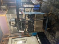
Here are some pictures of the welder and the conversion process (sorry the pictures are sideways):
image6.jpg
image7.jpg
image2.jpg


Back
Top