shepherm
Plastic
- Joined
- Oct 15, 2008
- Location
- Stillwater Ok
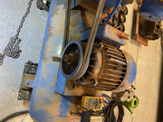
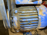
I have search and search, but haven't found a solution to my problem. So I'm going to see what you guys think, and thank you for any feedback you can provide. I bought this compressor yesterday from a guy who said it had low power. The motor data plate is missing, so I'm not sure if its a wiring issue or something else.
Here is a video of the motor running loaded and unloaded, and the wiring.
Youtube Video
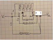
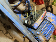
How it is wired:
Hot 1 => wire 1, 2, 8
Hot 2 => wire 3, 4, 5
Wire 1, 2, 3, and 4 are gray
Wire 8 and 5 are red
Wire 8 goes to four capacitors that are in series, and goes into the motor. I checked the capacitors and all measured within their printed microfarad.
I check the resistance between the wires:
1 to 3=> 1 ohm
2 to 4=> 1 ohm
8 to 5=> 1.4 ohm
Here is a video of the motor running loaded and unloaded, and the wiring.
Youtube Video
How it is wired:
Hot 1 => wire 1, 2, 8
Hot 2 => wire 3, 4, 5
Wire 1, 2, 3, and 4 are gray
Wire 8 and 5 are red
Wire 8 goes to four capacitors that are in series, and goes into the motor. I checked the capacitors and all measured within their printed microfarad.
I check the resistance between the wires:
1 to 3=> 1 ohm
2 to 4=> 1 ohm
8 to 5=> 1.4 ohm