What's new
What's new

Need help wiring Dayton motor to Dayton drum switch

JoggerBoy

Plastic
Joined
Apr 11, 2020
Hello everyone,

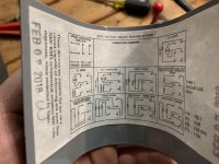
This is my first post on this site so excuse me if I don’t have proper posting etiquette. I need help wiring a 1hp Dayton motor (6k321) to a Dayton 3 pole drum switch (2x441). I’m looking to wire it single phase 240. Wiring is not my forte and I start second guessing myself if I look at it for too long. I’ll post pics of what I have below. I understand motor isn't wired for 240. the picture was when I first got it


8A9B191A-BC67-44DA-9841-B769093950B6.jpgIMG-1662.jpgIMG-1669.jpg8A9B191A-BC67-44DA-9841-B769093950B6.jpgIMG-1665.jpg
 
Your Drum switch is not quite correct for 240VAC. You can use 5 and 6 to remove one side of the 240VAC line but the other side is always connected. Being that 120VAC one side is neutral then 5-6 can be used for "On/Off" when connected to the "Hot" side of the 120VAC line. Connect 5 to "Hot" side and 6 to the motor. For Forward reverse Remove Red and connect to the Drum switch #1 connect where Red was removed from to #2 Remove Black and connect to Terminal #4 connect to where it was removed from to #3. Looking at the diagram with the switch in one position 1 is connected to 2 and 3 to 4, in the other position 1 is connected to 3 and 2 to 4. That is the interchange listed in the note. Center position all will be disconnected including input power 5-6.
As for voltage connect as shown but remember when connecting to 240VAC you are removing only one side of the 240VAC which is "Hot" on both sides. Old Code disconnecting one side of 240VAC was done. Be sure to ground the motor. If not the motor will become electrically "Hot" if something shorts.I see Brn connected to ground in 240VAC connection so I'm not sure if it will be a good idea to use this Drum switch for 240VAC operation.
 
Connecting the motor for 120v will bring the FLA to a smidgen under what a typical DCO (outlet) is rated for, which is 15 amps. That could be the proverbial fly in the ointment.

This is assuming this thing will be 'plugged in', which may not be the case.

Stuart
 
This diagram is similar to what you have. I can't read very well your motor connection diagram, but should be very similar to the one in this diagram. Your drum switch is a different brand, but the same contact arrangement.
Dayton1HP 230V FurnaceR44 .jpg

SAF Ω
 
I agree the diagram posted by SAF will work. The method will reverse the run winding that will not reverse the motor but will reverse start winding connection that will reverse the motor. Though I see no indication the motor posted by the OP has a Capacitor, it seem to be a Simple split phase motor. Probably don't need the extra torque because it's a Fan/Blower motor.
The motor connection in the photo is 240VAC and is connected as I would assume it's supposed to be in that the WHT (White) and BRN (Brown) wires are reversed and RED moved to the WHT connection allowing the start winding to operate at 120VAC. However the 240VAC connection diagram has me confused! The WHT and RED are connected as I assumed but the BRN is connected to Ground. Can anyone explain why? It makes no sense to me! Yes SAF's diagram will work for the motor in the diagram but how does it relate to the motor the OP posted?
20 Amp 120VAC outlets are available aotomarc. Amp draw listed when motor is under full 1HP load which in normal operation it's not especially if connected to a Machine like a lathe.
 
This diagram is similar to what you have. I can't read very well your motor connection diagram, but should be very similar to the one in this diagram. Your drum switch is a different brand, but the same contact arrangement.
View attachment 284724

SAF Ω

Sorry if this is a dumb question. Thanks for all the replies however, how do I know which color corresponds to which “T”. Sorry again if this is very basic stuff, first time wiring a motor
 
The capacitor housing is *just* barely visible in the first photo I believe. A wiring setup that provides full disconnect with a
240 volt supply. The drum switch is a different type however, also requires some digging to identify what wire goes where:

wire.jpg
 
I agree the diagram posted by SAF will work. The method will reverse the run winding that will not reverse the motor but will reverse start winding connection that will reverse the motor. Though I see no indication the motor posted by the OP has a Capacitor, it seem to be a Simple split phase motor. Probably don't need the extra torque because it's a Fan/Blower motor.

The motor connection in the photo is 240VAC and is connected as I would assume it's supposed to be in that the WHT (White) and BRN (Brown) wires are reversed and RED moved to the WHT connection allowing the start winding to operate at 120VAC. However the 240VAC connection diagram has me confused! The WHT and RED are connected as I assumed but the BRN is connected to Ground. Can anyone explain why? It makes no sense to me! Yes SAF's diagram will work for the motor in the diagram but how does it relate to the motor the OP posted?

For a explanation, I would suggest that you do a little homework for yourself. You make some assumptions, to guide the OP'er, most of which are factually incorrect. It doesn't help him by sending him down the wrong path. You could look up his motor model online, and clearly see that it is a capacitor start model, and not just a split phase. There is a internal connection diagram posted there, that shows that no internal leads are intentionally grounded.

However the factory diagram posted there, and the lead colors shown are slightly different from the model revision that he has. I had mentioned that the label shown of his motor was not clear enough to easily read, so I just posted a diagram for a very similar setup, for comparison. If he wanted or needed more specific help, it would be up to him to post a more legible data plate.

The same thing applies to the other commenters saying it should be wired for 120V to meet NEC code, and that the drum switch purchased is incorrect. Why would the manufacture list 115/208-230V operation as options, and a drum switch showing several motor types listed as suitable, including split phase and 3Φ ?

The poster upfront said that he is a green horn in connecting a drum switch and motor, does it help him any to submit incorrect information? Not intended to be critical just stating that it's unhelpful.

SAF Ω
 
I admit I did not look-up the motor, I used the wiring diagram listed. It states to exchange (as best as I can make out zooming as much as possible) RED and BLK (Black). I provided a simply connection to the drum switch as I could to someone that stated they were not familiar with drum switch connection. I didn't say the drum switch was not correct but that is was not correct to connect the motor for 240VAC operation given the diagram on the motor which at best is confusing. A number of correct diagrams have been posted but none the will easily instruct the OP in connection. I see in the terminal connection photo 4 wires that are supplied. Red, White Black and Brown, A green screw is also shown! In the 120VAC diagram a what looks like a ground symbol is shown with no connection to it. I assume it's the place to connect the ground wire. However in the 240VAC diagram as best as I can see is the BRN (Brown) wire connected to Ground!. It didn't make sense so I avoided attempting a 240VAC connection! I could be mistaken thinking it's ground when in fact it is a provided terminal. Not wanting to assume anything I provided a means to revering a 120VAC connection by reversing RED and BLK since only Red and BLK were mentioned in the reversing note. However the other connections provided will work but I see 1,2,3 and 4 marked terminals on the motor and 4 wire colors in the photos and your attempting to tell someone that knows nothing to interpret the connection designations! What I did was to make it simple, if you want to pontificate post the connections as shown in the terminal photo rather that a typical wiring diagram so that someone admittedly states he know nothing will be able to easily connect the drum switch.
I did look up the motor and seen quite a few connections including one that was exactly the same as the one SAF posted. But at all those I looked at none had the same terminal locations nor wire color. A few had the start winding colors as RED and BLACK but in color not spelled out. So reversing RED and BLK as I listed in the 120VAC connection diagram will work. Being there are only 4 wires in the photo other connections are made to the terminals that I can't determine what they are! So at this time I think it best for the OP to connect the motor as shown for 120VAC and reversing switch as I described until better connection instruction can be posted. If I had the motor I could easily provide the 240VAC connection using the drum switch available. I will continue searching so I can determine the motor terminations or at lest figure out. For example one diagram using the number listed on the motor in the photo did show the same terminal numbers but not in the same location!
 
There is now a sticky that has the diagram which Atomarc kindly provided.

That diagram covers the usual types of drum switch, so it is only necessary to check the drum switch type, find it on the chart, and see what has to be done. Then it is a question of the motor, whether it provides the wires needed.

I expect to add some sort of better procedure to follow eventually, but meanwhile the diagram is there.

The diagram has been updated to a higher resolution than it was originally.
 
dayton-Dayton wire diagram 1.jpg
Here is a diagram I found searching for 6k321BF. Shown is the thermal overload that has 2 connections probably one for low voltage and other for high as I did find other diagrams showing the change in OL connection for dual voltage operation. However the problem still exists as to the correct connection to the motor the OP requested. I see what I mistakenly thought was a ground symbol is the OL connection and it explains why the brown wire shown in the photo of the motor connection diagram is not placed where the white wire was removed.. I'm trying to reverse engineer the connections to determine what the terminal and wire colors do so as to make a proper 240VAC diagram the OP can follow. In looking at quite a few 6K321BF motor wiring diagrams the start winding coil wires as listed are shown to be Red and Black (75 & 76 in the drawing above) and the Capacitor and switch being a somewhat Gray so I don't know exactly what the Red and Black wires are in the connection diagram and motor wiring photos. If the wiring is as shown in the connection diagram the diagram will work BUT if from what I have seen the Red and Black (75 & 76) are the Start winding connections and the switch is connected internally the diagram will NOT work! It will blow the Capacitor. Quite some time ago I wired a few single phase motors that were connected so that a 3 phase drum switch would not work if both sides of the line for 240VAC operation were desired to be switched.
If the OP wants to run the motor on 240VAC like countless older connections I have seen switching only one side of a 240VAC line (old 3 phase did the same switched only 2 of the 3 phases) then using the connection description I posted earlier and motor wired 240VAC as shown it is currently connected in the photo will work! Simply put until I can confirm what Red and Black wires are I can't come up with a reversing diagram for the drum switch in hand so that both sides of the line are switched off for 240VAC connection.
I looked at the stickies but again the problem is in translation to connection shown and the wires and terminals available in the OP's motor. Having the motor in hand connection can be determined with the help of an OHM meter.
 
Hey guys, I used this diagram shown and the motor was initially running fine. Silent in forward and reverse. I started turning pieces on my lathe and noticed the motor started to smoke ever so slightly after about 30 minutes of use. I shut it off and sure enough, I didn’t notice the motor heating up. It was hot to the touch. Any ideas on what I screwed up. I went off this diagram above.
 
Provided you didn't notice the motor being "sluggish" while it was operating,
the motor was likely connected for 115 volts instead of 230 volts.

The motor ran for as long as it did... because it was likely shut off at times during its use
providing some cool down. Unfortunately, the motor must now be replaced.

There's somewhat of a lesson to be reminded of here related to relying upon the "street" for help.
Especially when it is related to electricity.

John
 
What connection drawing? Post 6&8 are the same 10 or the one I posted 14 that is somewhat similar to 6&8 except the Over Load Switch is shown. All of the connections diagrams were found in the google search I made including the one I copied and pasted. I mentioned they will work depending on how wires Red and Black were connected internally in the motor and that in many of the pictorial internal diagrams I seen for the 6K321BF motor Red and Black were not connected in a way that the diagrams provided will work! My suggestion is to connect one side of the 240VAC line to one of the screw terminals and the other screw terminal in the motor to terminal 5 in the Drum switch and terminal 6 to the other side of the 240VAC line if you want to run the motor on 240VAC and the motor is connected as shown in the photo.(photo connection is for 240VAC operation) Then connect the Red and Black as I described in post 2. That method will simply reverse the connections for Red and Black since there is no definite internal wiring diagram of the motor to determine if the start winding is as shown in the various connection diagrams posted above. The only other alternative is for you to get an OHM meter so that the connections can be confirmed. In my post I was saying the connection diagrams provided were assuming the start winding was internally wired a particular way and what I was seeing it was different! I didn't provide a diagram because I could not confirm how Red and Black were wired in the motor so rather than assume connection I avoided connecting voltage to either Red or Black and simply reversed the connection as stated in the connection diagram in the photo. I also said that it may not be possible to switch both sides of the line with the drum switch you have given the way the motor seems to be connected internally. For now try connecting the motor so that only one side of the 240VAC line is switched, it's not that terrible in that it was very common years ago, is it the best? NO but it will work. Later with an OHM meter internal connections can be confirmed so that it might be possible to connected the motor so that when OFF both sides of the 240VAC line are removed. Also as I have mentioned you can run the motor on 120VAC, there absolutely no difference in motor output, only difference is Amp. draw. And NO lowering the Amp draw will not change the cost of the power used because it's the same either way the motor is connected.
 
Provided you didn't notice the motor being "sluggish" while it was operating,
the motor was likely connected for 115 volts instead of 230 volts.

The motor ran for as long as it did... because it was likely shut off at times during its use
providing some cool down. Unfortunately, the motor must now be replaced.

There's somewhat of a lesson to be reminded of here related to relying upon the "street" for help.
Especially when it is related to electricity.

John

Well John, speaking strictly from the 'street'...you're a little off base sir. A motor can overheat and smoke a bit but not give up the ghost..happens more than occasionally.

I'm going out on a limb here and will assume the OP connected his motor for the proper voltage. Having said that, the motor may have been running in START rather than RUN which could be the reason for the overheat and smoke. Or, it could be a mechanical binding with the lathe...or a over ambitious cut on the material.

Needless to say, your attitude is quite arrogant, as well as negative..sir!:(

Stuart
 
It's obvious the motor is not connected properly, that's what I was trying to avoid. Quite a few connection diagrams were posted including mine but I was trying to point out that there are a lot of ways to connect the motor posted when looking up 6K321BF motor connections. I used the one to show the Overload. The problem is before connecting the motor the actual internal wiring of the motor must be known. Diagrams in 6 and 10 will work but show a different wiring of the start winding. Using diagram 6 to connect to a motor that is wired like the motor in 10 will not work. Furthermore as I was trying to point out the diagrams provided were not specific as to wire color and terminal numbers in the photo of the OP's motor connection port. The result was as if written directions were supplied but in a language unknown by the OP. The only option was to look at the reversing and voltage connections provided by the motor manufacture and make the connections as stated not adapt a wiring method assuming how the motor might be internally wired. That is why I recommended not putting any voltage on any of the start connections and do as was stated, reverse Red and Black wire connections and use the remaining single pole switch to connect/disconnect power. I am sure White and Brown are the Run coil connections and when as shown connect the run coil in series or parallel so as to change the voltage. The screw terminals are connected to the other side of each coil. BUT!!! I'm not sure how Red and Black are connected and as I mentioned in other posts what I've seen when looking at 6K321BF internal diagrams Red and Black are the coil wires connected to terminals T5 and T6 in the diagram posted in 14. The OP's only option without knowing the Exact Internal Connections of the motor is to connect the drum switch to perform as directed on the supplied motor connection diagram as I described!
Oh yeah, forgot to say; connect the ground to the green screw in the motor connection photo and to what looks like the ground terminal on the bottom of the drum switch. Also remember to remove any jumpers on the Drum Switch. The connection I describes will not have any drum switch terminals jumped to another as in a few diagrams.
 
Last edited:
Hey guys, I used this diagram shown and the motor was initially running fine. Silent in forward and reverse. I started turning pieces on my lathe and noticed the motor started to smoke ever so slightly after about 30 minutes of use. I shut it off and sure enough, I didn’t notice the motor heating up. It was hot to the touch. Any ideas on what I screwed up. I went off this diagram above.

As has been mentioned, we can't help any further without a better photo of the motor connection diagram and connection plate, it's illegible. Only guesses can be made, and that hasn't got you very far.

SAF Ω


Back
Top