What's new
What's new

Need some electrical help with these motor taps, and contactor/relays

SShep71

Hot Rolled
Joined
Sep 17, 2014
Location
San Diego, Ca
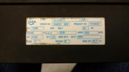
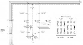
I am trying to wire up this Kaeser compressor model SK26. It is a 26HP motor, but it has a 12 wire system for star delta configuration. I haven't touched star delta in a long time, and when I did I had help. I don't want to mess this up so I asked a local electrician. He took a look at it and started talking about double "wye" and double "delta", which didn't make much sense to me. He then told me he wasn't super knowledgeable with this configuration. I asked him to just leave it go and I would do some searching around. Originally the compressor was setup for 460v three phase, but I am trying to wire it for a 230v three phase unit. I had started to move the connector bars before the electrician showed up. I wanted to know if anyone on here would be able to explain how this connection goes. I have only ever seen star delta setups with a main contactor and two relays for the delta-star sides. I really appreciate it any help.IMG_20191217_145537413.jpgView attachment 272911IMG_20191217_145427553_HDR.jpgIMG_20191217_145036433_HDR.jpg
 

Attachments

  • IMG_20191205_190629890.jpg
    IMG_20191205_190629890.jpg
    88.2 KB · Views: 129
  • IMG_20191217_145637077.jpg
    IMG_20191217_145637077.jpg
    95.6 KB · Views: 340
Kaeser SK26

Best thing you could do, is download a copy of the manual, it just requires a quick search.

After reviewing the official German print, slightly different from your rag, shows that is was configured with a Wye Delta starter, and a YY/ ▲▲ motor connection for low voltage operation.

Problem is, looks like you no longer have that setup any longer. You only have one main motor contactor, and a separate overload relay. Meaning its been changed to an across the line start.

The jumpers in the motor are partially correct for low voltage, but your missing a set, in your photo. Judging by the component and wire size in the photo, it might already be up-sized and connected for low voltage. Best bet would be to check the control transformer and see if it is strapped for low or high voltage.

Review the motor nameplate amperage's and KW, and compare to the ratings on your single starter and overload settings. You just might be setup for low voltage and across the line start already.

SAF Ω

272909d1576706437-need-some-electrical-help-these-motor-taps-contactor-relays-img_20191217_145427553_hdr.jpg


272913d1576706688-need-some-electrical-help-these-motor-taps-contactor-relays-img_20191217_145637077.jpg
 

Attachments

  • Kaeser SK26 Y-▲ Drawing .jpg
    Kaeser SK26 Y-▲ Drawing .jpg
    58.8 KB · Views: 875
  • 272913d1576706688-need-some-electrical-help-these-motor-taps-contactor-relays-img_20191217_14563.jpg
    272913d1576706688-need-some-electrical-help-these-motor-taps-contactor-relays-img_20191217_14563.jpg
    95.6 KB · Views: 65
That is what I was wondering. The manual I have shows the same as the faded panel mounted drawing. I took a picture when I got back and had the manual in front of me, I attached the wiring diagram and the panel layout diagram inline. The way it was setup, there were two sets of wires going to the motor taps U1 V1 W1 and U2 V2 W2. One set went up to the output side of the relay U1 V1 W1, the second set just went up into the cabinet and all three wires were capped together U2 V2 W2 (which is correct according to the panel drawing and the manual drawing for 460V at least). There were only three bars in the motor box, instead of six. I have to make up three more connector bars to tie the motor taps together for low voltage. The transformer was tapped for high voltage (center taps connected) but I had already switched it to low voltage (ends out tapped), according to the transformer diagram. The diagram included inline shows the cabinet in the manual the same way it is in the machine. This is where the confusion comes in. The motor box diagram shows Starting YY/service ΔΔ for 230v, and starting Y/service Δ for 460v. The diagram attached inline shows U2 V2 W2 tied together for 460V, but it shows it back to the starter for 230V. This is confusing. Where should the U2 V2 W2 connect back to for low voltage in the cabinet?
 

Attachments

  • IMG_20191218_192647738.jpg
    IMG_20191218_192647738.jpg
    90 KB · Views: 855
  • IMG_20191218_192624771.jpg
    IMG_20191218_192624771.jpg
    87.3 KB · Views: 134
Again you don't have enough contactors for Y/▲, Your setup is across the line starting only.

For 480V the 2nd half of the motor winding's run back to the terminal strip, and had shorting bars between them. This connects the motor in a single ▲, high volt- run mode (service, according to the motor connection diagram).

For low voltage operation the second half of the motor winding leads are moved over on the terminal strip, off of the shorting strip, to the V2,U2,W2 terminals. Where they then run back to the contactor load terminals and receive power. This power's both half's of the winding's in a ▲▲ mode, low volt run mode (service, according to the motor connection diagram).

But pay close attention to the phasing between the two half's of the winding's. You will notice that the phasing is reversed (rolled) between the two sides, of the stator winding's. Getting it wrong will produce bad results, the winding's will be pushing in opposite directions.

Make sure your contactor and overload is sized for the doubled current for low voltage operation.

272938d1576726538-need-some-electrical-help-these-motor-taps-contactor-relays-img_20191218_192647738.jpg


SAF Ω
 

Attachments

  • 272938d1576726538-need-some-electrical-help-these-motor-taps-contactor-relays-img_20191218_19264.jpg
    272938d1576726538-need-some-electrical-help-these-motor-taps-contactor-relays-img_20191218_19264.jpg
    90 KB · Views: 56
For the normal Y/▲ starter, with 3 contactor's, and the same 12 lead motor, this is the diagram I posted earlier, in post #2.

Notice it has the same phase rotation reversal from one winding half, to the next, shows up better in this style drawing.

272934d1576719439-need-some-electrical-help-these-motor-taps-contactor-relays-kaeser-sk26-y-drawing-.jpg


SAF Ω
 
I had to read the reply a few times, but now it makes sense (I think). So just to check and make sure I understand this, the U2 V2 W2 leads should go from the motor taps to the main magnetic contactor but, the U2 V2 W2 should be connected so that they are 120deg out of rotation from the U1 V1 W1. The U1 V1 W1 should go from the relay to the other half of the motor taps, with phase orientation normal. I will check to see if the ratings on the relay and contactor are high enough to handle the motor.
 
Sounds like you understand correctly now. Just follow the drawing exactly. If the wire tags are damaged, don't guess, label them.

L1 feeds U1, W2, -- L2 feeds V1, U2, -- L3 feeds W1, V2
If rotation needs changing, do that in the line side, before the contactor, Not at the motor side.

For the overload setting, the way it's connected, it's only seeing half of the motor current, so it should be set to that.

A tid bit on the two designs. The machine you have was built for the American market, across the line starting, heavier power grid normally.

The Y/▲ delta model I posted, is for the European market, or locations where the grid is not as robust.

SAF Ω
 
I just wanted to post an update, I wired everything up, double checked all the work still drops a breaker when I energize the motor. I took all the leads off the posts and there is a short inside the motor, it shows resistance where there shouldn't be any. I don't have anymore spare time to put into it, I gave it to my neighbor who said he will have a motor shop take a look at the motor.


Back
Top