What's new
What's new

Need Wiring Help PLEASE!

dezil

Plastic
Joined
Nov 14, 2012
Location
Northern new Jersey
Hello everyone, I am new here and not an electrician, but I have basic knowledge. I have a south bend lathe that I swapped the table and it came with a nicer motor that what I had previously, but now i cant get it wired properly.

Here is what I know:

The motor says "craftsman" but it was made by Emerson in the 60's....Here is a photo of the plate that's on it.IMG_20150117_184841_091-1.jpg

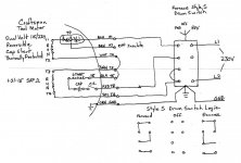
Here is a wiring diagram that I found online, it looks EXACTLY like what I have on the motor.IMG_20150118_103001_188.jpg

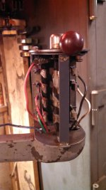
Here are some photo's of the switch. I know it is a furnas drum switch.IMG_20150118_190017_002.jpgIMG_20150119_121225_138.jpgIMG_20150119_121231_364.jpg

There is a capacitor on the motor that says its for 110v ( I am trying to wire it for 220v).

If you look at the photos the drum switch has 7 lugs or terminals, every diagram I have seen ( except for the one on the inside of the cover ) shows these switches with 6 lugs not 7......I cant figure out of I need to change the capacitor, some people say yes, others say it doesnt matter.

I am getting very frustrated, can someone please help me out....
 
Single Phase Drum Switch Connections

Dezil,

I suggest you have a look here, explains what your trying to accomplish, lot of good info already on this forum, suggest you learn how to search it.
This one is from the south bend section, which is where you came from.
http://www.practicalmachinist.com/vb/south-bend-lathes/wiring-issues-pictures-296475/#post2449633

Your drum switch is only slightly different than most but you already have the connection diagram for it, in the cover. The one that applies to your application is the split phase diagram, in the upper right.
Furnace 7 term drum switch.jpg

Forget the diagrams that you posted in your earlier thread here.
http://www.practicalmachinist.com/vb/south-bend-lathes/wiring-help-please-297598/#post2465693
It's not the same switch, nor the same motor. Use the diagram for your switch and motor, and post the connection diagram from your new motor. Only then will there be enough information to put it together.

As to the start capacitor, there is no need to change it for the higher voltage connection, if it is still functional. The motor windings will still power it at 120V, when connected according to the motor connection diagram.

SAF Ω
 

Attachments

  • Furnace 7 term drum switch.jpg
    Furnace 7 term drum switch.jpg
    95.1 KB · Views: 500
SAF,

First off thank you for responding and all of the information. I will follow the wiring configuration on the diagram inside the cover for "split phase" like you said, but I am confused about the motor. The craftsman motor is the motor I am using. The model is referred to as 113.12250, 113 being the code for the vendor emerson, and the model being 1225. The diagram I got from the internet shows a diagram for acraftsman (emerson) model 1225 to wire for 230v. You mentioned that this is not for my motor, Im not sure I am understanding here. The leads and colors I have on my motor are identical to whats in the diagram. There are no terminals to see or switch, the wires come out of the motor through a rubber grommet, unlike most motors I have seen. I looked at the link you gave me, but my motor is different than that. perhaps I am not understanding you correctly. I apologize if I am going in circles, but as I said I am new at this.
 
Well, I am ALWAYS suspicious of the "just do like this" instructions on the internet.... May be right, may be wrong, may be almost right, or may be badly wrong.

It looks like "badly wrong" is what is the case here.... the internet expert shows a 6 terminal switch , you have an 8 terminal switch. Just a tad different, eh?

Then also, the brown wire left out may be the protector.... (or not). It would be best not to leave out the protector, it has a purpose.

best thing is to KNOW what the wires do, then you also know WHY it has to be wired that way.

So.....

Is there a wiring compartment on the motor? Maybe not, since you say it has a grommet and all the wires come out there. I ask because it is common for the wiring instructions to be on a label stuck to the inside of the cover.

Are there numbers on the motor leads? Many motors have numbers printed on the leads, which usually correspond to industry-standard conventions for the different types of motor.

Your goal here is to turn the 230V on and off, and also to connect the start winding one way for forward, and the other for reverse. The wiring diagram given from the switch label posted by SAF shows the RUN winding being reversed, which will NOT BE CONVENIENT for a 115/230V motor, although it works for a 115V only, or 230V only motor.

For 230V you need to do it differently, you need to do the reversing on the start winding. You also have a motor protector, which should be wired in series.

Your switch isn't too bad,...... the lowest contacts appear to be a simple on-off switch. The top contacts and the 3rd down are also on-off, all of them on for either forward or reverse.

There is an added feature, because the switch also reverses the second from top contacts. In one "on" position, the left-hand terminal of the second pair is connected up to the top pair, while the right-hand terminal of the second pair is connected down to the third pair.

In the other "on" position, that is reversed, so left is connected down to the 3rd pair, and right is connected up to the top pair.

That action is what is needed to reverse a single phase motor. You use it to reverse the start winding.

To be sure, we need to figure out which two wires are for the start winding, and which two pairs are for the two run windings that are in series for 230V.

Right now, the only thing we know for sure is that the start winding is going to end up on the terminals second from top of the switch. It's not clear to me which wires they are on the motor, however.

What can you come up with as far as a wiring diagram for the motor? Inside of the wiring cover, something from the sears parts website, whatever...... needs to be for THAT motor, not from whatever the internet experts say.
 
Do this in TWO steps...

First wire as 120 volt if that is what the drawing is.

The windings are start and run.

Run windings are two tgat are wired in series for 240 or parallel for 120.

Never looked at how start windings are done but they seemed to work.

Once you get it working converting to 120 is simply changing a couple wires or leave it as 120 vac. As only 1 hp it does not make that much difference.
 
OK....just went out and looked again. There is no writing or markings on the wires. I have never seen a motor like this, usually its like you describe where there is a cover and a T1 and T2 terminal or something like that, this one is not like that, the one end is sealed, and has the shaft that comes out and a pulley, the other end has a centifical looking fan, and is screwed shut. The wires come out of a rubber grommet. There is no writing anywhere except the data plate I have the photo of. I called sears, and they researched all the numbers on that data plate. What they came up with was that it was made by emerson ( vendor number 113 ) and the model number was 1225...hence the 113.12250 model number. They also told me it was made in 1964. I have hunted all over, and that drawing i listed was all I could find that referenced the model 1225 for 230V and the drawing was put out by sears and roebuck, so I am guessing that is my best chance for a drawing.

As if that wasnt difficult enough, yes I have an unusual switch. All the diagrams I found were for a 6 terminal switch. I know for a fact that that switch does work. I broke my usual rule of photographing how it was put together before I took it apart, because I believed my electrician friend knew what he was doing. Hind sight is 20/20, how ever I would really like to learn WHY this works the way it does, and I am enjoying learning all this anyway....
 
Even though the wires come out of the grommet , there's an end plate on the motor unless it's the fan type end. If there is an end plate look behind it for connection and color code. You pictures are not clear about the wiring end. You may need to take the fan housing off , but first lets have a pic of the end and we'll go from there

I have the same PDF file
 
Your switch is fine, it's not even that unusual. It's one made specifically for single phase reversing, 3 phase needs only 3 wires and 3 switch elements.

The ones such as the internet reference, or the switch that SAF shows, are for 3 phase, but CAN be wired to work with single phase.
 
1 Phase Motor & Reversing Drum Switch Connections

This ought to fix ya. The actual motor lead color codes are similar to the NEMA standards, seemingly differing only on one color, GREEN in your case is T3 winding terminal, not a ground. However you also need to add a GREEN wire for the motor frame grounding, tap a 10-32 hole to attach one if needed.
DrumSwTypS-230V ConnDiag.jpg
SAF Ω
 
Dezil, glad to hear you have success. One additional tidbit suggestion. Since you had a hard time finding or making a diagram for your particular application, the suggestion I would make, is to make a copy of the one provided, and affix it to the machine somewhere. Then down the road when the motor start switch or cap fails on it, it won't be such a pain to remove it for repairs and get it hooked back up correctly.

SAFΩ
 
One step ahead of you, I laminated it and put it with all the other paperwork I have for the machine.....

Also one other question. I got my "emergency stop" switch, and its not a typical type of switch where it breaks the line going to the motor. I was told that there should be a 110v line to break and once that happens it will kill all voltage to the motor. The difference this time is I actually have a modern switch with all info available. Should I post up what I have, or is what I am saying making sense to a more educated audience than myself?

CUTLER HAMMER 10250T17213
 
Dezil, my suggestion was to put a copy of the drawing "on the machine" a copy in your file is fine for storage. Every time I go to service a piece of equipment they tell me the documentation is in the office, but cant produce it even when their business depends on it. Just adds extra BS and time to the troubleshooting and repair. I love equipment makers that can have a copy glued to a door inside, nobody can remove it without destruction to place in their office never to be seen again. You can then always get to it without delay, and take a photo if you later need another copy to "put in your files".

The switch you have is a mushroom head emergency stop, intended for placement in a control circuit, not directly in a motor circuit. The A600 type contacts are only rated for 3A breaking @240V and your motor full load current is more than 2X that, so if you used it on the motor directly likely wouldn't live too long, may just weld closed and cease to work. If you wanted to use it then you need to add a magnetically operated motor starter or motor rated relay, to handle the current safely. Would also need to add a Start button as well, and some more control wiring. Most old school manual machines just used the drum switch located for quick easy access for manual control. Newer codes requite the magnetic control for safety, no auto restart after a power outage and restoration is one of the main benefits.

SAF Ω
 
You make a very valid point. That nice laminated piece of paper will look good pasted to the inside of the door.

As for the switch I am confused by this. I expected a switch that has two legs ( one for each 110 line of the 220 ) and upon pushing the button it cuts all power to the motor. It was explained to me ( and me not knowing any better I assumed it was true ) that this is not a light switch, there is a line in the motor that if you break it, everything stops, and that's where you would use a switch like this. Do you think its useable?
 
Dezil, The switch has a normally closed contact with 2 connections, for a control circuit, not for power wiring to the motor. On your setup with a manual drum switch controlling the motor, you don't have a control circuit (low power), just line power (high power) with manual control. The description the seller gave is correct for a setup with a magnetically operated motor starter, but not for a manual drum switch controller. In your current setup with no magnetic starter, the switch is not useable, it's power rating is way too low to switch the motor circuit directly. It may work a few times before the contacts burn up from the motor current, this is not something you want to do, especially on an emergency stop circuit, it needs to be reliable and trusted to do the job.

Any switch you use in addition to the drum switch, needs to have a horsepower rated contacts, for the horsepower of your motor, otherwise it will surely fail. That is never a good thing on an emergency stop switch.

What you would need to do to use the switch is install a magnetically controlled starter or relay, and a control circuit. Then the E stop button contacts could be wired in the control circuit to cut off the starter.

SAF Ω
 
Deziel,

ok....is that difficult to do? Does it require changing the motor?

I'll let you be the judge of your skills. What you would need to do, like stated earlier, is install a magnetic starter inline before your drum switch.
Something like this.
http://dealerselectric.com/PESW-9V24AX-R28.asp

This is for three phase and will need a little modification in the wiring connections to make it work properly with single phase.
It also needs a start/stop button for it to work. You have a Mushroom stop, then would need to acquire a Start to go with it.

The button you have is a NEMA version, 1 3/16" hole, and will not fit the hole in the starter shown which is IEC version, 7/8" hole.
So to use the button you have would require a separate enclosure for NEMA type start / stop buttons mounted on the front of the machine.
Then the magnetic starter could be mounted on the rear of the machine or the wall behind it. To stay code compliant, the motor starter would also require a disconnect switch right next to it or within 25' of the circuit breaker and still visible.

As you see this is a bit more involved to have the safety feature, of the magnetic starter and E stop button. Nowadays this would be mandatory requirement in any workplace.

Wether you want to go the extra distance for the safety is up to you, it's your digits, eyes and limbs at risk. In a workplace there could be costly fines for not having it.

SAF Ω
 
SAF, thank you for the explanation. I understand it now. I would feel a lot better having an emergency stop, but that's one huge hassle. It was such a job to get it to work, I am not ready to undertake another project like that. I am surprised no one makes a emergency stop switch that just breaks both 110 lines of the 220v.....thats what I thought I was buying.


Back
Top