What's new
What's new

No Load Motor Temperature Rise

ptsmith

Cast Iron
Joined
Feb 15, 2018
I'm reluctant to post this because it's another one of my stupid blunders.

I have a new 2HP 3 phase motor with 9 wire voltage configuration. I hooked it up wrong. Really wrong. It wasn't running anywhere close to right, but I was testing a used VFD and assumed it was the problem. Eventually I thought to feel how hot the motor was and it was pretty hot. So I checked the wiring, found and fixed the mistake.

It seems to run fine, but worried about damage, I waited until the next day, let it run and kept track of it's temp with a temp gun. This is no load on the motor. The motor is clamped to a table. The VFD is set to 60Hz.

Prior to running, it measured 90F.

10 min. 110

30 min. 136

45 min. 145

60 min. 155

I stopped there. I assumed this is bad but I can't find anything that touches on this so I don't know.

I checked my 3HP Lagun mill for comparison. VFD set to 60Hz. It does have the load of the vari-belt and spindle load so it's not an exact comparison.

I only did one reading at 10 minutes. Starting temp was 81F and the 10 minute mark reading was 106F.

I was surprised by this. As far as I know the mill VFD and motor are working fine. I've never had any trouble out of it. At the 10 min. mark it rose 5 degrees more than the motor I thought was toast.

So does anyone have experience with this?

Thanks.
 
are you sure you have it wired right?

a 2 hp motor should be on the order of 200 watts no load power consumption max.
amps on each phase are on the order of 1/3rd nameplate full load amps.

a 240v motor once its up to speed should run fine on single phase 120v 60hz. (hard to do this safely btw, you'll need to quickly unplug it from the vfd and then plug it into an outlet. if the motor slows down and stops (unplug it before it does or you can fry the windings) then something is wrong.
 
assuming the motor is wired now correctly and has an integrated fan to move at least some air around it, under no load it shouldn't get warmer than what you would feel comfortable holding your hand on

if you have connected it correctly, and it gets hot under no load at normal rpm, then most likely there is a short in the windings, depending on where the short is, you might or then again might not be able to measure it with a regular multimeter, meaning - if the short is between few enough windings, the ohmmeter might not have enough of resolution to measure it, inductance should be measured instead to compare the condition of windings
 
At NO LOAD, a standard induction motor will draw perhaps 40% of full load current. The temperature rise is usually due mostly to current, the insulation and magnetic losses are generally minimal. So, neglecting those, the dissipation in the motor will be about 16% of that at full load.

While that sounds small, it may be enough to raise the temperature significantly, leading to someone thinking that the motor is "running hot". It might be, or it might not. The temperature in a motor is generally hotter than what you would want to put your hand in, or on. Even 16% of the power can raise the motor temperature to what YOU consider "hot".

Trying to diagnose the health of a motor when some other person describes it as "feeling too hot" is pretty much not a useful exercise. I would not advise extensive testing and worry based just on an "impression" that the motor is "too hot". Now, if we are talking "boiling spit", then there may be some cause for alarm, depending. That would give a rough temperature reading.

A much more reliable means of determining health is to look at the current. Or, a real temperature reading of the motor can be helpful, one that gives temperature in degrees.
 
most motor bearing grease is rated 200F or 300F.
.
unless motor over 190F you not near any normal limits. some motors running air compressor the air compressor can get over 250F easily, due to compressing air creates heat. this heat can easily effect motor alignment. quite often one end of motor hotter than the other so shafts do not go up evenly
 
At NO LOAD, a standard induction motor will draw perhaps 40% of full load current. The temperature rise is usually due mostly to current, the insulation and magnetic losses are generally minimal. So, neglecting those, the dissipation in the motor will be about 16% of that at full load.

While that sounds small, it may be enough to raise the temperature significantly, leading to someone thinking that the motor is "running hot". It might be, or it might not. The temperature in a motor is generally hotter than what you would want to put your hand in, or on. Even 16% of the power can raise the motor temperature to what YOU consider "hot".

Trying to diagnose the health of a motor when some other person describes it as "feeling too hot" is pretty much not a useful exercise. I would not advise extensive testing and worry based just on an "impression" that the motor is "too hot". Now, if we are talking "boiling spit", then there may be some cause for alarm, depending. That would give a rough temperature reading.

A much more reliable means of determining health is to look at the current. Or, a real temperature reading of the motor can be helpful, one that gives temperature in degrees.

Very well said.........
 
Thanks for all the responses.

It's wired correctly now. My error was in assuming motors are all wired the same. I used a downloaded a schematic to wire it which was not correct for my motor.

That's why I said it was a *stupid* mistake.

A much more reliable means of determining health is to look at the current. Or, a real temperature reading of the motor can be helpful, one that gives temperature in degrees.

Actually I posted detailed readings. I stopped at the 60 minute mark because I had other things to do.

Prior to running, it measured 90F.

10 min. 110

30 min. 136

45 min. 145

60 min. 155
 
You guys are not completely agreeing with each other. That's making me all the more confused. ;)

I'm not that good with a meter. I have a decent Fluke and would prefer not to toast it measuring current. Can someone explain the proper way to do that?

For measuring inductance, do I need to disconnect the VFD? Here's how it's wired for low voltage. What points do I need to read?

24710d1280159856-230-460-wiring-15hp-idler-motorwiring1.jpg
 
JSTs comment regarding subjective temperature measurement was directed at my post, which I formulated to be easily understood and so that suggestions I mention don't require special equipment or electronics knowledge to apply and diagnose the problem

I assumed wrongly that it is common knowledge that "comfortably warm" is around ~40C(104F), hot is 50C(122F) and barely tolerable is ~60C(~140F), above that I personally can't hold the palm of my hand against the hot surface for more than a few seconds
 
If you have noticed with a RPC generator motor:

Turn on a RPC and the motor makes some noise and there might be vibration. The motor voltage/current imbalance does that. When you turn on the load the motor quiets down. The larger the imbalance the more heat. Cooper Electric pdfs explain about this. In your case I suspect there is some damage which is causing imbalance.

If you doubt that then check what switching frequency the VFD is running on. If it is high like over 8k then try setting it down to 4K or 5K. If the heat goes down then the switching frequency has something to do with it.
 
And.... the nameplate on this motor says what for max. temperature?

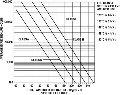
It only list ambient temp., 40C. Class B insulation. See chart below.


This chart from your last link says that Class B insulation is good for 1,000 hours at 170C/338F. I could live with that, assuming it doesn't get hotter than that under load. If it's damaged maybe it will though.

PLE130910_EASA_Insulation_Temperature.jpg
 
If you have noticed with a RPC generator motor:

Turn on a RPC and the motor makes some noise and there might be vibration. The motor voltage/current imbalance does that. When you turn on the load the motor quiets down. The larger the imbalance the more heat. Cooper Electric pdfs explain about this. In your case I suspect there is some damage which is causing imbalance.

If you doubt that then check what switching frequency the VFD is running on. If it is high like over 8k then try setting it down to 4K or 5K. If the heat goes down then the switching frequency has something to do with it.

Carrier frequency is something I've looked into before. I'm pretty certain that motor temp goes down as the frequency goes up, and VFD temp goes up. And vice versa. I have it set to 15Kh for noise reasons. This doesn't seem to bother my Hetachi WJ200. The VFD temperature after an hour had only increased 6-10 degrees. I don't remember the exact number.
 
I forgot to mention that I checked the RPM while checking the temp. It remained at 1,795 the entire 60 minutes. Don't know if that's informative of anything or not.
 
Carrier frequency is something I've looked into before. I'm pretty certain that motor temp goes down as the frequency goes up, and VFD temp goes up. And vice versa. I have it set to 15Kh for noise reasons. This doesn't seem to bother my Hetachi WJ200. The VFD temperature after an hour had only increased 6-10 degrees. I don't remember the exact number.

You almost had me believing that.
 
It's pretty obvious I know very little about any of this. So maybe I've misunderstood what I've read. I looked into it quite a bit in the past in regards to carrier frequency noise.

VFD switching frequency and its affects on distortion and output

As the switching frequency increases, motor heating due to higher harmonic content in the current waveform decreases. At the same time, the heat generated internally in the VFD due to the IGBT switching is increased.

AC Drive Carrier Frequency

As the inverter’s carrier frequency is increased, the output current waveform supplied to the motor becomes more sinusoidal. This improved output current waveform decreases motor heating thus improving motor insulation life.
 
For measuring current, you want a clamp-on meter, or adapter that will work with the fluke to measure current. Fluke has many of them, and they sell current meters, as well as meters that have a clamp-on current probe but also measure volts etc.

The clamp-on type do not require any disconnecting of wires, etc, you just clamp the probe around the wire, It is best if the meter reads "true rms", but averaging type meters will give at least a "relative" reading.

Fluke Tools Current Clamps | Fluke


Back
Top