Hi,
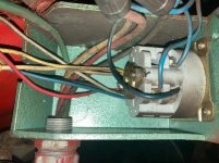
I picked up a small gearhead drill press recently. While labeled TMA, it is tagged as having been manufactured by Bergman Borr in Sweden. The motor has six wires. Three appear to be cream or white, one red, one blue and one black. The wires are labelled S1, S2, S3, B1, B2, B3.
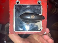
These wires run to a drum switch which only has two positions marked with a 1 or 0. Since I never saw the machine wired in, I have no idea if this is a reversing switch (why on a drill press), or a on off switch (most likely).
The only tag on the machine indicates it can run at 220 or 440 on a 60hz frequency. It gives no indication as to the wiring required, delta or wye. The lead coming into the switch box is 4 wire, black, white green and red.
I need to make sure this is wired for 220v to work on my VFD.
In trying to research answers myself I have seen reference to a resistance chart. If it would help for me to measure resistance across the six wires, let me know and I will do that.
I have included as many pics as I can, any pointers would be hugely helpful, thanks.
TAG

Wires in switch box

Drum switch, inside and front


I picked up a small gearhead drill press recently. While labeled TMA, it is tagged as having been manufactured by Bergman Borr in Sweden. The motor has six wires. Three appear to be cream or white, one red, one blue and one black. The wires are labelled S1, S2, S3, B1, B2, B3.
These wires run to a drum switch which only has two positions marked with a 1 or 0. Since I never saw the machine wired in, I have no idea if this is a reversing switch (why on a drill press), or a on off switch (most likely).
The only tag on the machine indicates it can run at 220 or 440 on a 60hz frequency. It gives no indication as to the wiring required, delta or wye. The lead coming into the switch box is 4 wire, black, white green and red.
I need to make sure this is wired for 220v to work on my VFD.
In trying to research answers myself I have seen reference to a resistance chart. If it would help for me to measure resistance across the six wires, let me know and I will do that.
I have included as many pics as I can, any pointers would be hugely helpful, thanks.
TAG

Wires in switch box

Drum switch, inside and front


