Chaval AlHazman
Plastic
- Joined
- Sep 26, 2020
I purchased a Maka Mortiser which was in use in Germany running on 380v. I rewired it to run my shop voltage line at 240v (off of my AR 20 RPC)
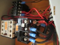
One of the main changes needed was to replace the overload relay, so that it can accommodate the higher amperage. The original OR I removed was an older Siemens Overload Relay- I installed a newer Schneider that can work at my current 8.5A capacity.
My problem is that my machine is not running properly. This machine is designed so that when the Start button is pressed- the chisel head moves from its starting position and advances horizontally (I believe this is via its pneumatic control- not sure yet) which soon trips the motor upon reaching a position that is manually preset. This is the point where the swing-chisel begins its job, digging out a mortise. However with my machine as soon as the chisel head is tripped on- it stops advancing! It stays in this mode (spinning/oscillating) until I press a button which returns it to starting position
I believe I got something wrong when I replaced the overload relay. I thought I did a good job in maintaining the original wiring configuration, but they both have a different layout, so I must have gotten something wrong. Specifically, the original OR had a short wire that ran on its underside from the A2 port to 96, It also had the single wire from the corresponding A2 terminal in the contactor running into the top of the OR. But on the new one (Schneider overload relay) there is no port for A2, so I ran a wire from the A2 port on the contactor all the way straight to the 96 terminal.
Any suggestions?