What's new
What's new

Please help with capacitor sizing for 7.5 HP RPC

cgrutt

Aluminum
Joined
Apr 7, 2016
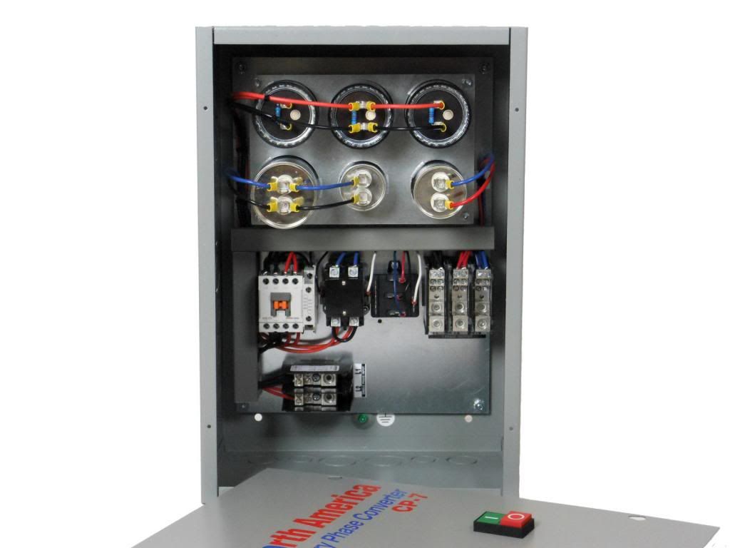
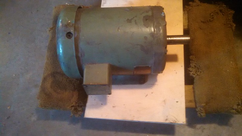
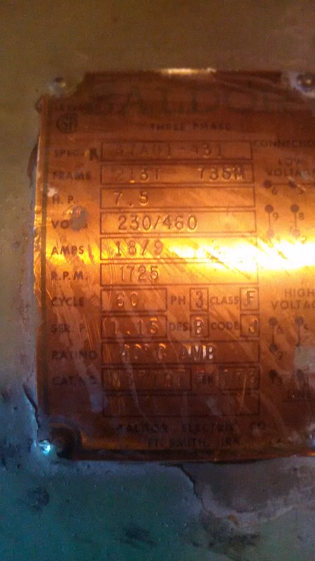
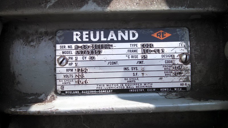
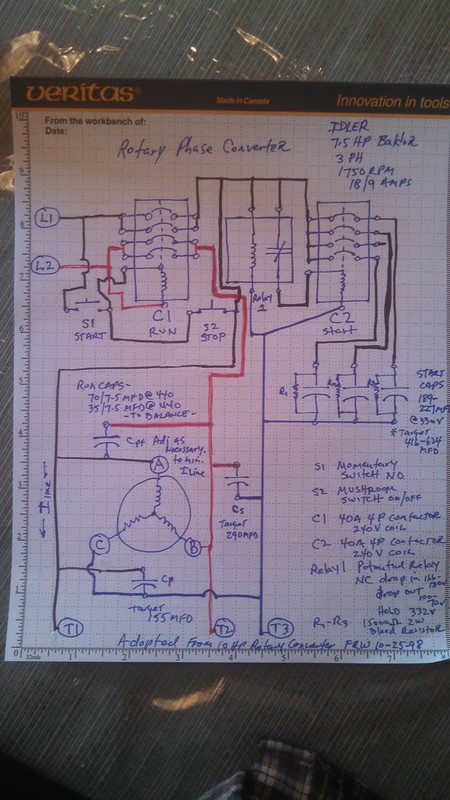
Picked up a Baldor 7.5 HP 3PH 1750 RPM motor to build a Rotary Phase Converter today. Want to build it to self start and with voltage balancing. Been reading a lot of great information within this forum and others and think I've got the basic gist of it but need help with choosing the right capacitors (I'm sure I'll need help with other stuff later, LOL).

So read in another post a "guideline" for capacitors for a generic 1 HP 3 PH RPC is 1 start capacitor of 100 MFD @ 250V and 2 run capacitors of 10 MFD of @ least 300 VAC and this guideline remains pretty much linear for larger motors. Based on this, I believe I will need 1 start cap of about 750 MFD @ 250 VAC and 2 run caps of about 75 MFD of @ least 300 VAC. Is this right so far?

I looked at some caps online and found some have multiple MFD ratings e.g., Jard #11952 start cap is rated 216-259 MFD @ 250V 11952 - Jard 11952 - 216 - 259 MFD Round Start Capacitor (25V) Do you use the low, high or maybe average MFD rating when choosing the correct cap? Would three of these run in parallel give me the approx. 750 MFD @ 250 VAC that I need based upon guideline?

Also for the Starter Cap, is it a good idea to use a "bleeder" resistor to discharge cap after RPC is running and it is taken out of circuit? If so, can anybody recommend the appropriate resistor to accomplish this?

As far as the run caps, will 2 of the Jard #12899 12899 - Jard 12899 - 8 MFD Round Run Capacitor (37V) be a good choice for my application?

Are these even the right caps to be looking at? Should I be looking at different styles, etc.?

Finally, do these capacitors provide the necessary "balancing" voltage for the "phantom" leg of the RPC.

Appreciate your help. Been reading about this for hours and haven't stumbled upon a cookie cutter parts list for a 7.5 HP RPC. If anybody has one, I'd appreciate it if you would point me in the right direction.

Thank you.
 
It's not really a cookie cutter application!

Grab some of the "rule of thumb" caps and start in. They don't need to be costly, nor even new!

Run caps can serve as start caps, but not the other way 'round.

Yes, put on some bleed resistors! 10K+ 1/2 watt should do. It's a matter of time to discharge and not burn up the R.

Read more, try some things, It's not rocket surgery!
 
A 7 1/2 hp idler

I connect about 400-600 µF start cap, Black to blue, at 330v, I use 2w bleed resistors per can.
I connect about 125-150 µF run cap, Black to blue, 450v
I connect about 70-85 µF run cap, red to blue, 450v

You're balancing caps are a little heavier on the same side as you're start caps. The split is usually close to, but not definite 2/3 black, 1/3 red, at 30 uf/hp idler. So... 225 uf total is your ballpark for run capacitors.

Your main contactor should be able to handle 2 1/2 times your idler Apps at single phase. Your start cap Contactor can be a simple air conditioner rated for 30A but sharing contacts. And all contactors you can always up them to Nema to be safe.


Thank you!
 
I'm starting to think I might be better off buying a pre-made unit such as this one...

DSCN7241-2_zpsc5b7cb79.jpg


$229 includes:

* Built-In Motor Starter with Start/Stop Switch
* Digital Controlled & Protected Start Circuit
* Complete Phase Power Failure Protection
* Precision Voltage Balancing
* Power "ON" Indicator Light
* Easy Installation
* Distribution Block Connections
* Power Factor Corrected
* Made In the USA
* Lifetime Warranty

CP 7 Pro Line 7 5HP Rotary Phase Converter Control Panel Loaded with Features | eBay

Pricing things out and costs are starting to add up:

About $100 +/- in caps (various sizes to "size" for my idler)
$50 for a 40a 3 Pole run contactor
$40 for a 30a 3 Pole start contactor
$10 for bleed resistors
$25 +/- for start/stop switches, terminal strips, misc., etc.
$50 for steel enclosure

So $275 +/- just for parts.

Am I missing something? I thought an RPC was supposed to be "dirt" cheap, LOL (Yeah, I realize you can build it using a piece of rope to start it without any voltage balancing)...
 
Or bare bones for $169

s-l500.jpg


Looks like this is missing balancing caps but includes start and run contactors, push button start/stop, etc.
 
Your term "balancing caps" are actually called run capacitors. They are the tin can ones
to the left of the black start capacitors. The electrical components are most probably cheap
chinese ones. And the enclosure is one of the cheapest styles you can get. I found a new stainless
steel Hoffman 12x14 box with hinged door for $45 in a surplus store 5 miles from me. Online
the price is $600 - $800 on ebay. Ebay is BS. Look at surplus outlets.

A more important issue is what you are trying to balance. What is the horsepower of the motor
you will be connecting in parallel to your 7.5 Hp idler. To suggest a set of balance caps without
that information is just guessing, Mr Spock would say "non sequitur".


By "Balance Caps" I meant configuration of the run caps such that the voltage drop across three poles are close to same voltage at given load (ie Vab approx. equal to Vbc approx. equal to Vac).

So are you suggesting that if I spent the $275 the components would be better than what I would get if I bought a pre-made box? If that's the case I can appreciate it and am willing to spend the money, it just seems the components are generic. The brand name caps that I was looking at (e.g., Dayton) are now made in China.

This is the motor I picked up for the RPC 7.5 HP Baldor:

25792453614_e2fc436f15_c.jpg


25792439184_109f979931_c.jpg


This is the lathe motor it will be providing power for Rueland 3 HP:

26211813991_44a211f661_c.jpg


26277992765_a5706d86f0_c.jpg
 
Do you also have a little 1/4 or 1/2 hp motor? With one of those and a couple pulleys and a belt only thing else you need is a light switch for the little motor, and a 2 pole magnetic contactor big enough for your 7.5hp idler.

You can add the run capacitors later as you find them cheap, or forget about them.

Nothing wrong with a phase converter in a box but you could start cheap and simple now and get fancy later if you want.
 
Thanks. I prefer to have it start up with the start caps. Don't mind spending the money to build it myself if it results in a better system, I just was comparing prices of the parts to a pre-built system and it seems it's a lot cheaper to buy one already made. I expected it to be cheaper to build it, LOL...
 
Both of the manufactures that you provided, I have worked on. The first one uses a IEC Contactor 12 amp per contact. The contacts are shared so you get maximum 24 A Single phase 240 V. It is a decent set up and well worth the money. It is a fairly well-balanced well-designed unit. The only thing it lacks is a better contactor.

The second unit, I don't like their layout, I don't like their layout, I don't like how they balance all from one side with the run caps.

Both units use the air conditioner contactor to disengage start capacitors.

The first unit is better balanced. But this does not mean it will be balanced 100% to your motor. They do have a 24 hour hotline for help if required.

I use IEC and Nema, IEC is generally specific and if applied properly is very robust. Nema on the other hand applied is always robust. Nema size one contactor is rated for 27 A per contact at 240. But for single phase they only have a rating of 3 hp. They can totally handle 5 hp with two contacts single phase. Now a size one Nema with three phase can handle 7 1/2 hp. This is what it's really rated for, three phase. If you take A 4 contact Nema size 1 and do what they did with the IEC contactor shown in your first picture, you would be able to provide 54 A single phase. Just imagine if you ran 2 size 1's three contact Nema in parallel you could throw 81 A safely.

Hunting eBay will run you a medium dollar. Definitely source your scrap dealers for scrap prices. Most often electricians won't instal used equipment. And there is no market for scrap, except for guys like me and maybe you. A brand-new panel I can get for about $12 on hinges. But I built the die that stampped it. Retail it runs around $27 for 6×18×18. The stainless steel cabinet, my cost is about three times the price new.

Capacitors I generally like to source New unless I am confident they are good and I can repurpose. Mexico and China has taken over the capacitor trade for the most part.

If you're looking to build, I'll send you the 2w bleed resistors for free.
 
Wow, thanks again. So do I have the parts that I need right?

- various size caps to "size" for my idler
- 6 Dayton 105-126MF 220-250v start capacitors (total up to 630-756MF)
- 6 each Dayton 12.5MF, 25MF and 50MF at 440v (total up to 525MF).
- 40a 3 Pole run contactor
- 30a 3 Pole start contactor
- bleed resistors (appreciate your offer but have no problem ordering them)
- push button momentary NO start switch
- Pull NC off switch
- steel enclosure

Do I need a transformer for coils or do I operate these at 120v? 240v? If I use transformer, do I create DC from bridge rectifier and run switching at 24v DC?
 
What are your contactor coil voltages? If you're running a line, are you bringing along neutral, is neutral already there? I don't mind other designs, but I hate using transformers in the panel if they can be obsolete.
 
Haven't run anything or ordered anything yet. I can run a neutral no problem. Or I can buy contactors with 220 coils. Either way makes no difference I just want to be sure I'm ordering right parts. Thanks.
 
Well I'm committed now. Received a 20% off coupon from Zoro this am and went ahead and ordered the caps and bleeder resistors. This is what I ordered, hopefully will be able to configure it properly. All the caps are Dayton.

Starter

Three 189-227 MFD @ 330v should give me ability to go approx. (based on average value) 416 MFD or 624 MFD on starter circuit.

Run

I bought "dual" run caps which I understand combine two caps in one case so should provide lots of tuning options

Four 35/7.5 MFD @ 440V and Six 70/7.5 MFD @ 440V should give me up to 635 MFD total.

Working on sourcing 2 NEMA 1 rated 3 pole contactors on ebay. I believe they are "new old stock" that someone picked up from a company that went out of business and had them in inventory. $20 each.

Need to source a potential relay but not sure what cut-in/cut-out voltage to look for.

Also need to source a cabinet.

Coming along...
 
Seller got back to me about NEMA 1 contactors and coils are wrong voltage.

So I just ordered two new Definite Purpose 40A 4 Pole contactors. I'll use one for the Line in and double up connections as suggested and the other for the Starter circuit with one starter cap off each of three poles. Could have ordered a 30A 3P and saved a few dollars but figured might as well keep everything at 40 A.

Ordered a 35A potential relay with pick up of 166-180V, Hold of 332V and drop out of 100-70V. Saw this on another design that was posted on another thread. Hope it's the one I need, LOL.

So should have everything to get started building in a couple days. Still need to source an enclosure but want to lay everything out to see what size will work best before ordering this. Also need to pick up some wire in right colors. Assuming solid 10 GA is way to go? Stranded would be easier to work with if this works.

Appreciate any tips or advise or if I ordered anything that won't work.

Thanks!
 
"New old stock" you are starting to learn...

Before buying a cabinet:
Get a piece of scrap plywood and build the rpc on it.

Lots of discarded cabinets everywhere I go. Holes can be filled with custom
turned coins and welded in place. Then surfaced and painted to look new.

Instead of a 30A start contactor, these days I would use a SSR.
 
First off I would like to say thanks for the suggestions and help. Really appreciate it. Secondly, I take no credit for below, it largely follows a document I came across on the Internet (may be from this forum but I read through a bunch of stuff over the past week or so and don't recall where I got it), 10 HP Rotary Converter by FRW 10-25-98 and incorporates some other things I've read or suggestions from members here (shout out to Matt Matt!). So does this look about right? Any suggestions for safety and/or improvement is much appreciated.

26415238355_9840b4daa9_c.jpg


RPC is started by pushing momentary switch S1 which trips Contactor C1 (40A, 4P with 220V coil) providing line power to Idler motor terminals A and B and the Starter circuit Relay 1 (Potential Relay NC with pick up voltage of 166-180V, drop out voltage of 100-70V and Hold voltage of 332V). This immediately trips Contactor C2 (same specs as C1) and engages Starter Caps, which each have 15K 2W bleeder resistors to discharge capacitors when not under power. As voltage is sensed on the phantom leg T3, Relay 1 should trip disengaging C2 and taking Starter Caps out of circuitry. C1 also provides feedback of L1 to itself in order to keep live line current flowing after system is started and S1 is opened. Opening Stop Switch S2 cuts the feed back circuit which disengages C1 and powers system down.

Run caps are placed across each of the output feeds T1-T3, T2-T3 and T1-T3. The first two values are initially set at values suggested by Matt Matt. The last is per original design and is adjusted to minimize Line Current at T1 while Idler is running without load. Values of all Run caps need to be determined while system is operating under load to balance voltage output across each terminal.


Back
Top