bnelson
Stainless
- Joined
- Dec 11, 2002
- Location
- Carmel, Indiana, USA
The recent thread, 220 panel & ground has raised questions from some PM members about the 120/240 volt system we have in our homes.
At the risk of being pedantic, I thought a bit of a tutorial, by way of a dry cell experiment anyone can easily do, would help with the understanding.
This is the Edison 3-wire system which is used in homes.
As an example, consider two dry cells, each 1.5 volts, connected in series as shown above. The voltage between legs A and B is 3.0 volts, while the voltage between the neutral and either leg is 1.5 volts.
Now imagine two lamps, each 1.5 volts and equal current. If you connect one between leg A and neutral, it will light up. The same with leg B and neutral.
Can you see if you connected both lamps up, one on leg A and the other on leg B, that both would light up, and both would stay lit even if you cut the neutral?
With the load equally balanced between legs A and B, the neutral current drops out, as you have, essentially, both lamps in series across 3.0 volts.
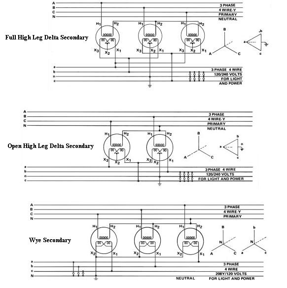
This is exactly how it works in your house. In this case, the 'battery' is the secondary winding of the transformer, with both ends of the coil tapped as well as the center of the secondary coil. The center tap is what we call the neutral conductor (white insulation). This conductor is grounded to the earth, both at the transformer and at your house service entrance. Thus you can touch the live neutral conductor without getting any shock, as it is at zero volts with respect to earth.
Each of the phase legs (either black or red insulation) is at 120 volts potential with respect to the neutral. But the potential between both phase legs is 240 volts. The phase leg conductors are often called the 'hot' or 'live' wires.
Circuit breakers or fuses are put on the phase conductors only, NEVER the neutral. That's why a 120 volt circuit has a single width breaker, while a 240 volt circuit such as your air conditioner has a double-width breaker -- one for each leg. Circuit breaker panels are designed so that any two adjacent vertical slots will tap opposite phase legs.
Although the neutral conductor is always grounded, it almost always carries current. The only time it wouldn't is if the load were exactly balanced on legs A and B.
On the other hand the equipment grounding conductor (green insulation, or bare wire) never carries current except in the case of a power surge or a ground fault. The reason is that the equipment grounding conductor is connected to the metal frame or chassis of a tool such as an electric saw. The neutral wire going to the saw carries 120 volts, as does the hot wire. If the neutral were to become abraided and touch the metal chassis, you would not get shocked and the saw would keep running (although this would not be a great situation).
Without the grounding conductor, if the hot wire were to touch the chassis of the saw and you were standing on wet earth, there's a very good chance the saw would keep on running and you would get electrocuted as the current passed through your body to earth, but at not sufficient current to trip the breaker.
However, with the grounding conductor properly in place, any current from the hot wire would instantly be diverted to ground. You would feel no shock. And the short to ground would also trip the breaker, immediately shutting the saw off.
You can see just how important proper grounding is from the standpoint of life safety. I wish people who cut off the grounding prong on a male plug so it will fit into a two slot receptacle could read and understand this.
For big home devices such as your water heater and air conditioner, there may not be any neutral at all. Frequently these devices are wired with only the two phase legs to feed the load, and a third wire to serve as the equipment grounding conductor for safety in case either hot wire should accidentally touch the metal frame.
At the risk of being pedantic, I thought a bit of a tutorial, by way of a dry cell experiment anyone can easily do, would help with the understanding.
This is the Edison 3-wire system which is used in homes.
As an example, consider two dry cells, each 1.5 volts, connected in series as shown above. The voltage between legs A and B is 3.0 volts, while the voltage between the neutral and either leg is 1.5 volts.
Now imagine two lamps, each 1.5 volts and equal current. If you connect one between leg A and neutral, it will light up. The same with leg B and neutral.
Can you see if you connected both lamps up, one on leg A and the other on leg B, that both would light up, and both would stay lit even if you cut the neutral?
With the load equally balanced between legs A and B, the neutral current drops out, as you have, essentially, both lamps in series across 3.0 volts.
This is exactly how it works in your house. In this case, the 'battery' is the secondary winding of the transformer, with both ends of the coil tapped as well as the center of the secondary coil. The center tap is what we call the neutral conductor (white insulation). This conductor is grounded to the earth, both at the transformer and at your house service entrance. Thus you can touch the live neutral conductor without getting any shock, as it is at zero volts with respect to earth.
Each of the phase legs (either black or red insulation) is at 120 volts potential with respect to the neutral. But the potential between both phase legs is 240 volts. The phase leg conductors are often called the 'hot' or 'live' wires.
Circuit breakers or fuses are put on the phase conductors only, NEVER the neutral. That's why a 120 volt circuit has a single width breaker, while a 240 volt circuit such as your air conditioner has a double-width breaker -- one for each leg. Circuit breaker panels are designed so that any two adjacent vertical slots will tap opposite phase legs.
Although the neutral conductor is always grounded, it almost always carries current. The only time it wouldn't is if the load were exactly balanced on legs A and B.
On the other hand the equipment grounding conductor (green insulation, or bare wire) never carries current except in the case of a power surge or a ground fault. The reason is that the equipment grounding conductor is connected to the metal frame or chassis of a tool such as an electric saw. The neutral wire going to the saw carries 120 volts, as does the hot wire. If the neutral were to become abraided and touch the metal chassis, you would not get shocked and the saw would keep running (although this would not be a great situation).
Without the grounding conductor, if the hot wire were to touch the chassis of the saw and you were standing on wet earth, there's a very good chance the saw would keep on running and you would get electrocuted as the current passed through your body to earth, but at not sufficient current to trip the breaker.
However, with the grounding conductor properly in place, any current from the hot wire would instantly be diverted to ground. You would feel no shock. And the short to ground would also trip the breaker, immediately shutting the saw off.
You can see just how important proper grounding is from the standpoint of life safety. I wish people who cut off the grounding prong on a male plug so it will fit into a two slot receptacle could read and understand this.
For big home devices such as your water heater and air conditioner, there may not be any neutral at all. Frequently these devices are wired with only the two phase legs to feed the load, and a third wire to serve as the equipment grounding conductor for safety in case either hot wire should accidentally touch the metal frame.