Don Kinzer
Cast Iron
- Joined
- Mar 18, 2002
- Location
- Portland, OR USA
In researching further, I found a potential relay with 50 amp contacts that may be suitable for use in rotary phase converters, especially larger ones. A data sheet for the device, called a Universal Motor Starting Relay, can be found at the URL below. It is available from a variety of sources including amazon.com where I bought it for $13.50 including shipping.
http://www.icmcontrols.com/ProdImages/ig_LII332.pdf
The device has the same connection regime as other commonly used potential relays like the Steveco 90-66. However, it is a bit more sophisticated than the typical potential relay because it has extra circuitry that implements a "safety timeout". I haven't seen an explicit description of what this does but my assumption is that it will open the contacts after a period of time even if the drop out voltage has not been reached.
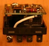
There has recently been another thread regarding a replacement for the Steveco 90-66 in an application where that potential relay needs to be modified to separate the relay contact terminals from the coil terminals. With that in mind, I opened up the UMSR-50 to see if it could be modified similarly. What I found looks promising but I have not actually tried it.
The first and second photos show some of the internals with annotation indicating which terminals are which.


The third photo shows the single-sided printed circuit board that contains circuitry to control the relay coil. I've shown on this photo where a trace could be cut (using a Dremel moto-tool, Exacto knife or something similar) to separate the contacts from the coil. After doing this, it would be necessary to drill a hole through the case near the T4 terminals and connect a wire from T4 to the isolated end of resistor R1 (on the corner of the PCB). After making this modification, the coil terminals would be T4 and T5 while the relay contact terminals would be T1 and T2. Given the voltages involved, the cut in the trace should probably be at least 1/4" and a wider cut would not hurt.

An alternate method of modifying it would be to de-solder the lower end of resistor R1 and drill a hole through the PCB a safe distance away from the pad, making the connection to T4 from the free end of R1. Here again, a 1/4" or larger separation would be advisable.
I plan to install the (unmodified) UMSR-50 in my RPC some time in the next few days to see how it works as a direct replacement. I'll report back when I have results.
http://www.icmcontrols.com/ProdImages/ig_LII332.pdf
The device has the same connection regime as other commonly used potential relays like the Steveco 90-66. However, it is a bit more sophisticated than the typical potential relay because it has extra circuitry that implements a "safety timeout". I haven't seen an explicit description of what this does but my assumption is that it will open the contacts after a period of time even if the drop out voltage has not been reached.
There has recently been another thread regarding a replacement for the Steveco 90-66 in an application where that potential relay needs to be modified to separate the relay contact terminals from the coil terminals. With that in mind, I opened up the UMSR-50 to see if it could be modified similarly. What I found looks promising but I have not actually tried it.
The first and second photos show some of the internals with annotation indicating which terminals are which.


The third photo shows the single-sided printed circuit board that contains circuitry to control the relay coil. I've shown on this photo where a trace could be cut (using a Dremel moto-tool, Exacto knife or something similar) to separate the contacts from the coil. After doing this, it would be necessary to drill a hole through the case near the T4 terminals and connect a wire from T4 to the isolated end of resistor R1 (on the corner of the PCB). After making this modification, the coil terminals would be T4 and T5 while the relay contact terminals would be T1 and T2. Given the voltages involved, the cut in the trace should probably be at least 1/4" and a wider cut would not hurt.

An alternate method of modifying it would be to de-solder the lower end of resistor R1 and drill a hole through the PCB a safe distance away from the pad, making the connection to T4 from the free end of R1. Here again, a 1/4" or larger separation would be advisable.
I plan to install the (unmodified) UMSR-50 in my RPC some time in the next few days to see how it works as a direct replacement. I'll report back when I have results.


