diesel-xj
Aluminum
- Joined
- Sep 27, 2011
- Location
- South Texas
Good afternoon all. I have a new to me Motoman UP6 robot arm with a XRC control. I revived my old home made RPC to run this machine. The RPC ran my old mill with no problems. i switched to a VFD when i got another machine. I had both machines running off the one VFD (one at a time with a 3pole double throw switch).
Well one salt water flood later, the VFD was toast, but the RPC was above the high water mark. so some new wiring and we are back in business.
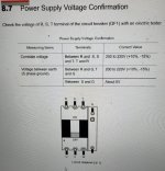
Now for the new 20 year old robot. The Motoman XRC control is set up for multi voltage, it has a big transformer in the enclosure with 3 taps for 240, 480, 560 in, and one 240v, or 208v output,not sure what the output is actually suppoosed to be just yet. Motoman said+ 5%, minus 10% on voltage is ok
I hooked it all up, and i was able to boot up the old robot, but ran into trouble while changing the CMOS battery. I thought i killed it dead. but a few phone calls and it is back up and running. But one of my problems at least i think, I had a low voltage leg. I traced this back to the transformer still being hooked up, and running 208 into the transformer and getting 175v on one leg out of the transformer. I figured I did not need a transformer at all, going fromm 208 to 208. So just bypassed the transformer all together. and i have
L1-L2= 207
L1-L3= 238
L2-L3= 214
l1-gnd= 118
l2-gnd= 172
l3-gnd = 119
ground here being the case of the control
I am afraid to run that high voltage manufactured leg into my old control. I only get one shot at this thing. burning up a control board in the 20 year old robot control will pretty much brick the whole operation
I was reading a voltage control thread gman4405's . i like the idea of moving the manufactured leg to some system that is not so voltage critical. But i dont' know which system that would be. I near as i can tell. there are 3 ish subsystems . 1. the main control (computer), 2. the servo drives, 3. the brakes and other . and then all the low voltage stuff for the encoders, and maybe the brakes as well. Since there is no dumb spindle motor, i can't go there. The whole load on the system is tiny 1.5KVA. I am running a 3hp home made RPC
So the question is How can i reduce the manufactured leg down a bit in voltage. I don't know how to get a reading on this while under load. I have not even got one servo to move yet, let alone all 6 servos together.
is there a calculation for a capacitor that uses HP of the RPC
then my next question is pretty basic, But i am running a 3 wire 220vac single phase system , hot, hot neutral. I think i want to put in a real ground for the robot. But in my junction box the ground and the Neutral are still jumpered together, I know that is not the modern way. but that is how it is set up at least for now
in a modern system the neutral stays isolated until it get to the first box at the service disconnect, correct ?
Well one salt water flood later, the VFD was toast, but the RPC was above the high water mark. so some new wiring and we are back in business.
Now for the new 20 year old robot. The Motoman XRC control is set up for multi voltage, it has a big transformer in the enclosure with 3 taps for 240, 480, 560 in, and one 240v, or 208v output,not sure what the output is actually suppoosed to be just yet. Motoman said+ 5%, minus 10% on voltage is ok
I hooked it all up, and i was able to boot up the old robot, but ran into trouble while changing the CMOS battery. I thought i killed it dead. but a few phone calls and it is back up and running. But one of my problems at least i think, I had a low voltage leg. I traced this back to the transformer still being hooked up, and running 208 into the transformer and getting 175v on one leg out of the transformer. I figured I did not need a transformer at all, going fromm 208 to 208. So just bypassed the transformer all together. and i have
L1-L2= 207
L1-L3= 238
L2-L3= 214
l1-gnd= 118
l2-gnd= 172
l3-gnd = 119
ground here being the case of the control
I am afraid to run that high voltage manufactured leg into my old control. I only get one shot at this thing. burning up a control board in the 20 year old robot control will pretty much brick the whole operation
I was reading a voltage control thread gman4405's . i like the idea of moving the manufactured leg to some system that is not so voltage critical. But i dont' know which system that would be. I near as i can tell. there are 3 ish subsystems . 1. the main control (computer), 2. the servo drives, 3. the brakes and other . and then all the low voltage stuff for the encoders, and maybe the brakes as well. Since there is no dumb spindle motor, i can't go there. The whole load on the system is tiny 1.5KVA. I am running a 3hp home made RPC
So the question is How can i reduce the manufactured leg down a bit in voltage. I don't know how to get a reading on this while under load. I have not even got one servo to move yet, let alone all 6 servos together.
is there a calculation for a capacitor that uses HP of the RPC
then my next question is pretty basic, But i am running a 3 wire 220vac single phase system , hot, hot neutral. I think i want to put in a real ground for the robot. But in my junction box the ground and the Neutral are still jumpered together, I know that is not the modern way. but that is how it is set up at least for now
in a modern system the neutral stays isolated until it get to the first box at the service disconnect, correct ?