What's new
What's new

Rotary phase converter problem : video attached

rule308x

Plastic
Joined
Apr 20, 2012
Location
USA, Near Nashville Tennessee
Hello,
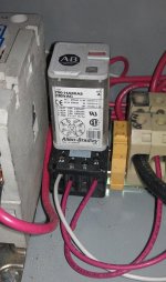
My 15 hp rotary phase converter, which has been working fine for months, is having a problem. I don't have the schematic and did not build the unit and am looking for help diagnosing and fixing the problem. It is wired to a 220v 60 amp breaker and has been powering a 6.75 hp nardini lathe. When it is switched on the idler motor comes up to speed quickly and quietly and stays running. When a load is applied (lathe turned on) the contactor sputters and arcs (see video).


I'm not an electrician but I can use a multimeter. I've pictured the box and the major components below. I can provide more pics and information if that will clarify.
uc

uc

uc


I would be grateful for any help diagnosing the problem or suggestions for fixing the problem. I'd be willing to replace the automatic components with manual switches if necessary.

Thanks,
Jeff
 
Sounds and looks like the load from the lathe is pulling the coil voltage down to the point the contactor is "chattering". Try moving the coil to a different connection, or try operating it independently of the rpc. A third thing to try is to manually close the contactor by pushing on the moveable contact carrier in the middle with a insulated tool.

Tom
 
Thanks Sir.
I'll try to manually close the contact tomorrow and report back. I'm afraid I don't understand what moving the coil to a different connection means...I think it's operated by the relay to the right of it. Could I just install a switch and power it from a separate breaker? I know it's basically a magnet that pulls down a bar that closes three connections, right? Might the magnet not be strong enough to hold the contacts down? Thanks again for the insight.
I'm hoping its something easy and cheap to fix and not a problem with the lathe motor.
I'll let you know what happens manually closing the contacts as soon as I try it.

Jeff
 
It has been my experience that when the driven motor (lathe) is connected, that the generated leg voltage will drop until the starting current goes to running current. Starting current is usually about 6 times the running current. That voltage drop can be enough for the contactor to drop out, interrupting the current to the lathe motor, the generated leg voltage then rises back to the open circuit voltage, the lathe motor tries to start, dropping the voltage and on and on and on. The arcing you see is the contacts opening and closing rapidly. By rewiring the coil to another source other than the generated leg, the coil voltage stays solid and the motor will start normally.

Tom
 
Tom,
I tried pushing down the contactor center but all that happened was that the idler motor made a "grinding" type noise and seemed to slow down until the contactor was released. I moved the connection to the relay that switches the coil from the generated leg and got the same noise upon startup. I tested the voltages when the converter is running with no load and I think they are pretty high, between 260 and 270 volts, with the generated leg being on the high side of that range. The voltage from the breaker is also about 260V. I cleaned the contacts on the contactor and it does not seem to be chattering anymore, but the lathe still does not start... just a "thunk" noise. I double checked all the wires from the lathe to the converter and I'm showing the same voltages at the lathe as at the converter terminals.
One of my problems is that the design of this converter does not seem to conform to any of the three designs I've seen posted here.

Also, I see that my pictures from my original post are not showing up, perhaps because I should have sized them down before posting. Here they are in more manageable size. Is there a way to delete the original picture links to prevent anyone from wasting their time downloading them? I wonder if that's why I have not gotten more responses.
I'm very grateful for your help so far Tom!
Contactor.jpgConverter.jpgRelay.jpg
 
Is that contactor connected to the start caps? I dont see drain resisters on the start capacitors. If this is true, the contact points are probably charred from breaking with a high amount of current (from the start capacitors) passing through.
 
I am thinkin the cube relay is for the start circuit (seems kinda small) and the #1 starter was the run for the idler. After hearing the story I was wondering if you have ventured over to the lathe and checked the motor over there for a short or an open winding?
 
I was just studying it some more. The cube looks like a off delay timer much like i use for my converters.
I believe the poles are jumpered together on the main relay as well. That's what initially led me to believe it was being used for the start caps.
regardless, the start caps will inialiate any relay contacts without the 15K resisters.
 
True. I don't give that little relay much of a life expectancy (even if it did have the resistors) after burning up a contact or two on larger relays myself. Even so, if the start circuit was boogered it cause problems before the load was applied. It seems in this case he has voltage on all three legs and a smooth running idler. When he tries to start the lathe it sounds like a much larger load is being applied than what should be expected. That's what makes me think he might be looking at the wrong piece of equipment.
 
Let's recap. The RPC was working with the lathe fine until recently. Yes? If yes, did you change any wiring, or did it just quit working properly. Can you substitute another motor for the lathe to check the RPC? Can you trace out the wiring to make a diagram? Include the line and load wiring, not just what is in the box. The arcing contactor appears to wired in parallel to form a single pole contactor that appears to be switching the caps.

Tom

Yes, the lathe was starting fine until recently. I didn't change any wiring and it just quit starting the lathe and started arcing when I tried to do so. Unfortunately I don't have another motor that I know for sure works...I have a questionable one and I'll try it, but if it doesn't work it won't tell us anything definitive. I'm in the process of sketching a wiring diagram and will have it up in a bit.

I'm also going to check the lathe motor for shorts.

The Lathe is Nardini with a 6.75 HP dual speed motor that I just received last month. The dealer tells me that the motor has been professionally rewound just prior to shipment. When I received the lathe the high speed motor setting was reversed, but I had not messed with it because I have not needed the higher speeds yet. I figured that since it was a 3 phase motor I just needed to switch two wires and that when the rewound motor was reinstalled the tech just reversed those two wires.

I sure hope the lathe motor isnt the problem...

Thanks again for all your help. I'll get the diagram up asap.

Jeff

Thanks
 
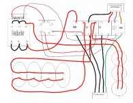
diagram.jpg
Heres the diagram. I'm sorry for the poor quality. I did not show the output to the lathe because the diagram was already getting cluttered. The connections to the lathe are as follows:

White wire to GEN
Black wire to L1
Red wire to L2
Green wire to Grnd

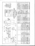
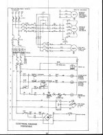
here's the nardini wiring diagram:
Nardini.jpgnardini1.jpg

Thanks,

Jeff
 
First things first. Is the diagram the way it is wired now or before I suggested moving the coil leads?

The way I believe the unit was designed is that the AB relay was being used as a potential relay, its contacts are normally closed. One leg of the relay is connected to L1 (T1) or L2 (T2) and the other leg was connected to the generated leg (T3) of the idler motor. When power is applied to the RPC, there is no output voltage on T3. Current flows from L1 through the NC relay contact through the size 1 contactor and to neutral, closing the contactor and connecting the round capacitors, the ones on the right, from L1 to T3. These are the starting capacitors. The other bank of capacitors are the running caps.

As the idler motor starts and comes up to speed, the control relay gets voltage from T3 and operates, opening the connection to start contactor. In other words, it is acting like a timing relay.

As it is wired now, the AB relay is wired between L1 and L2. It operates as soon as power is applied to RPC and stays on. The start capacitors are never in the circuit and the idler will not start or as you say growls.

Connect the control relay back to the way it was. The idler should now start and run smoothly as before.

Now back to the original problem, the arcing of the start contactor when the lathe is turned on.

If you go back and look at the video at the beginning of this post, and watch the control relay, there is a window on the front of the relay upper right that signals the state of the relay, open or closed. Notice that the relay is chattering. Since it is drawing its power from the generated leg, the generated leg voltage is dropping as I originally suspected and causing the relay to drop out and reclose. Something is dragging the voltage in the generated leg down.

I have to go fix dinner, so I will continue afterward.

Tom

I am back. BBQ baby back ribs, escalloped potatoes, garden raised tomatoes home made BBQ sauce, yum.

As an experiment I would disconnect the contactor coil, hold it in with a rod until the idler motor is running and release. If you have a clamp on ammeter, I would check the phase wires while trying to start the lathe. The control relay may chatter, but since the contactor is disconnected, this is no concern. Also check the phase voltages. My guess there is something going on in the lathe, not necessarily the main motor. Just have to do some sleuthing.

Tom
 
Last edited:
I was just studying it some more. The cube looks like a off delay timer much like i use for my converters.
I believe the poles are jumpered together on the main relay as well. That's what initially led me to believe it was being used for the start caps.
regardless, the start caps will inialiate any relay contacts without the 15K resisters.

The data sheet for the Allen-Bradley part describes it as just a relay with 240 Volt coil. Your coil
voltage is not remaining stiff.

Another point is that it is a terrible idea to use soldered wires on you capacitor bank.

You should redesign the way the timing relay operation. You could get a real delay timer
and plug it into the same socket and move a few wires around.
 
Tdegenhart:
I'll have to get some help to try some of those diagnostic steps...the RPC is several feet away from the lathe, so I'll need someone to throw the switches. I'll report back..

From what I'm hearing, it sounds like I might have a problem within the lathe itself, but there are some things that could be improved in the RPC. What would be the cheapest way to improve the reliabablity of the RPC to the point that I could safely rule it out as the problem? Adding a real delay timer and capacitors? Changing the contactor? The capacitors were already soldered when I bought the unit, would it be better to unsolder them and rewire with connectors?

The motor does not seem to be shorted out. I turned on the lathe this morning and it haltingly rotated a few revolutions (while the contactor chattered in the background) before stopping. As soon as I get someone over to help I"m going to try disconnecting the contactor coil and dropping out the start capacitors manually, then try the lathe. I do have an clamp on ammemeter so I'll report those findings probably early tomorrow morning as I am off to work in a few.

Thanks,

Jeff
 
You could redo the start circuit as rons suggested, that's the way my rpc is wired, with a timer. If you decide to do that then the timer coil would be wired between L1 and L2, so that when power is applied to the rpc and as long as it is applied, the start circuit operates only once. Not familiar with AB part no.s so cannot help there.

Tom
 
Okay,
Tried removing the relay completely, starting the rpc with the contactor manually pressed and releasing when the idler motor came to speed (about 1 second, maybe less). The RPC started up fine and idler ran smooth. Turned on the lathe and switched it to run forward and the RPC idler motor began to grind or growl...similar noise as when I pushed the contactor button manually when the rpc was already running, adding the start caps back in.

Tested the voltages at the lathe when the RPC is running:

1-2 273V
1-3 253V
2-3 253V
1-GND 127V
2-GND 233V
3-GND 126V

Wondering if i've got something wired wrong or if I need to start looking at the lathe being the likely problem.

I accessed the lathe's motor and, even though the dealer told me that it had been rewound prior to shipping to me it does not look like the motor has ever been out of it's mounts. Hmmm.


Jeff
 
Did the motor attempt to run or just growl? Can you measure the line currents? How about current in the ground leads or neutral. Have you meggered the motor to ground and to each other. Can you isolate the drive motor from the rest of the control by either unwiring it or remove heaters. Then check the rest of the circuits including the coolant pump.

Tom
 
Sorry for the delay in reply...worked some extra shifts this week.

The "growling" came from the RPC idler motor. The Lathe stuttered but not much more. It's obvious it's getting power, just not enough to get it spinning. OR it's getting what it should and there's something wrong with the lathe.

I'm reading my multi-tester manual and will test the line currents in the morning. I'm not 100% clear on how to test the lathe motor because it's internals look a little different than the other motors I've see. It's a dual speed WEG made for Nardini with nonstandard wiring. Not sure how, or if, this affects the testing to ground protocol. Not sure what "heaters" are in the circuits, I believe I can isolate the motor.

I appreciate you hanging with me here, Tom and others

thanks,

Jeff
 
The strange thing is that you said this arrangement was working before and now its not??? At least that what you said in post #17. From what you have said so for, I would either judge that, a) something has happened to the motor to draw more starting current or, b), the spindle motor is under load at starting, such as a stuck brake. Make sure the spindle motor is turning freely. What about a loose power wire to the motor, such that it is trying to start single phase. In your machine wiring diagram, there is a symbol to the left of the main motor that looks like two hooks connected back to back labeled 1OL. That is an overload relay and it might have heating elements that I referred to as heaters. Check that for continuity.

This is like doing heart surgery over the phone.

Tom


Back
Top