Vladymere gr
Hot Rolled
- Joined
- Dec 10, 2008
- Location
- Charlotte, NC
Gentlemen,
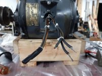
I have a 3/4 HP three phase motor in WWII vintage south bend lathe that I am cleaning and re-wicking.
This motor was manufactured by Wagner Electric Corp. It is a 220/440 volt motor. MY RPC is a 220 volt design.
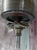
One of the three phases of this motor is a start winding. This start winding has a capacitor and a centrifugal switch in series. When the motor starts the centrifugal switch opens and this winding with capacitor is no longer powered.
As the motor is being run by an RPC I am thinking that the RPC high leg should be tied to the start winding. I have no reason for thinking this other than gut instinct. Does this seem appropriate?
Also the motor would not start so I replaced the capacitor which resolved the problem. The replacement capacitor I used is a 105 mfd, 240 volt. Does this seem an appropriate size? it does from the charts I found online.
Thank you for your assistance.
Vlad
I have a 3/4 HP three phase motor in WWII vintage south bend lathe that I am cleaning and re-wicking.
This motor was manufactured by Wagner Electric Corp. It is a 220/440 volt motor. MY RPC is a 220 volt design.
One of the three phases of this motor is a start winding. This start winding has a capacitor and a centrifugal switch in series. When the motor starts the centrifugal switch opens and this winding with capacitor is no longer powered.
As the motor is being run by an RPC I am thinking that the RPC high leg should be tied to the start winding. I have no reason for thinking this other than gut instinct. Does this seem appropriate?
Also the motor would not start so I replaced the capacitor which resolved the problem. The replacement capacitor I used is a 105 mfd, 240 volt. Does this seem an appropriate size? it does from the charts I found online.
Thank you for your assistance.
Vlad