Bear with me guys and be kind - I ain't THAT dumb ('cause all smart people say "ain't", right?) but I'm a bit perplexed here - a common condition according to my fiancee...but she said YES so joke's on her, eh?
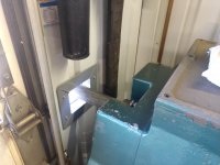
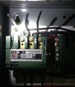
This is a '60s 17" SB Turnado with a Furnas box like this on the back. Clearly all this goes to the motor so what I need to know is where to attach my 4 wires in my power cord?
IIRC this machine "idles" the motor at all times and then engages the headstock as called upon, if that matters. This is one of the "good" Turnados made in IN, not the French electromagnetic whatchamacallits.
I see the ground up top, but definitely not certain on the 3 legs? Based solely upon loose screws I see one connection lower right (finger) and two matching up top LEFT and RIGHT of the green. But is that correct? Or should I be connecting at the black box up top?
Also I'm 99% this is already wired for 220 but can anyone tell?
There's no schematic on the outside or inside of the box but I did find this paperwork in the sheetmetal enclosure.
I'm grateful for any advice - I figure I might as well make the best of this virus downtime and get this machine under power! I saw the machine under power when I purchased it (so it works) from a trade school, but I'm embarrassed to say for how long it's sat here (years) waiting for nothing but a power cord....sad kinda.


")