What's new
What's new

TECO L510 Question regarding carrier frequency

ridgewaybodies

Plastic
Joined
Jun 30, 2011
Location
Greensburg, PA
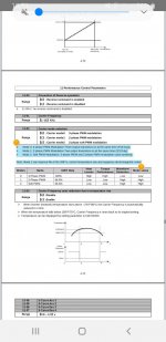
Can somebody explain in laymen's terms what this all means? Attached is the manual description. I have the Teco connected to a Alliant mill with the factory Asian 2HP motor. The motor has a pretty powerful fan on rear. Should I set this parameter on 3 PH? Advantages/Disadvantages. The manual is saying it will get hot. Would it be the motor or the VFD getting hot? I have the VFD mounted on the wall in a steel NEMA box and my need to ventilate it with a fan if the VFD gets too hot.Screenshot_20200425-105348_Hancom Office Editor.jpg
 
Last edited:
The "carrier" is the number of pulses per second used to create the output power waveform.

If low, you can hear it, which can be loud and annoying. If high, it increases heating of both the VFD itself, and potentially the motor.

The designers should have allowed only a "safe" range for the settings, and there should be no issues at any available frequency under normal conditions. If the environment is hot, ventilation is poor, load on the VFD is heavy, etc, then it may be better to choose a lower frequency carrier.

There is no need to set t higher than what keeps it from being annoying.
 
In regards to the drive mounted in the enclosure on your wall, it is usually mounted on its own big heat sink base, and if you punch holes in the top and bottom of the enclosure the natural thermal air movement will be adequate to keep the drive safe. The drive manufacturer often has minimum enclosure sizes listed for the drive that will allow proper cooling when non ventilated.

They usually stay cool so it's not a huge deal.

Stuart
 
Increasing the carrier frequency above 10kHz moves the high pitched whine from the motor out of the range of typical human hearing (but your dog may not want to hang out in the shop). If you are older like me, it might be as low as 5kHz.

But increasing it increases the switching losses in the VFD transistors, so you must de-rate the VFD output. If you have already de-rated the VFD for a single phase input, you have ended up with an over sized output anyway. Teco should give you guidelines somewhere for their drive, if not, 10kHz usually requires about a 20% de-rate with most drives, 15 kHz would require even more.

Increasing the carrier frequency also increases the negative effects that a VFD has on the motor circuit in terms of reflected wave voltage spikes on the winding insulation and any possible bearing damage. But if this is a 230V application, those risks are low to begin with, so may not be significant.

What is best for the motor is the lowest possible setting you can live with.
 
Thanks for all the replies...makes more sense and the frequency thing. . I forgot to attach the pic from manual. I just not understanding the mode thing. I'm wondering if I should change the mode to 3 phase.
 
Not every manufacturer requires a de-rate of output current for frequencies that will be OK on the ears.

For the very highest frequency choices, they may. Those are often so high that you have little need to use them.

The need for de-rating may depend on mounting, on ambient temp, etc as well as frequency
 
It looks like the default setting for 11-02 is '1'. I would leave it on this. Setting it to 0 would likely require derating the drive, on top of any derate for ambient temperature.

It's saying it will increase the drive's heat dissipation.
 
That is different, it is the modulation pattern being set by 11-02. Parameter 11-01 sets frequency, and 11-04 sets or disables a frequency reduction if the drive gets hot, which might be a good idea.

You could set the frequency to high enough that you do not hear it as a problem (maybe 8 kHz if you have typical hearing loss) and then enable the frequency reduction at high temps. The modulation pattern would depend on what you need, since it affects motor torque (and also noise).

The modulation pattern is really setting how many IGBTs are on at one time. More is more dissipation and less noise, but less is less torque. The dissipation reduction is by the average current per IGBT over time (since fewer are on at a time), and by having 1/3 fewer turn-on and turn-off events.

Techie details:

Dissipation in IGBTs comes from three main sources... Turn on/off losses, conduction losses, and "tail current" which is really part of turn-off losses.

When not conducting, the IGBT has a high voltage across it, but only a tiny leakage current flowing, so volts x amps is low, and there is nearly zero dissipation.

During turn-on, the IGBT has to change from high voltage across it but no current, to lots of current but very low voltage across it. During that time taken to change from one mode to the other, it is operating in "linear" mode, meaning that it has substantial voltage across it and current flowing through it, so dissipation is higher, volts x amps is a bigger (but changing) number. You control this by the control voltage input, the faster you change that, the less dissipation (and the more electrical and radio noise).

When it is conducting full current, it has (should have) a low voltage across it, even though it has maximum current, so volts x amps is again low. The designer of the VFD has little control of this other than by assuring full control voltage, and choosing the best device type to use.

Turn-off is like turn-on, except it is commonly slower, so dissipation is higher.

The "tail current" is unique to IGBTs (Mosfets do not have it). IGBTs conduct with two types of "charge carriers", electrons, and "holes", which are where there IS NO electron, but there is a place for one. Both can move (in opposite directions) to conduct current. After the device has been "turned off" (the control signal has been totally removed), those two types need to "recombine" in order to totally shut off current. Until they do, there is a low current still flowing, which is a significant contributor to dissipation. The manufacturers have really cut down on that by various means, the designer has little control over this aside from carrier frequency.


Back
Top