What's new
What's new

Transformer vampire draw: the plot thickens

JasonPAtkins

Hot Rolled
Joined
Sep 30, 2010
Location
Guinea-Bissau, West Africa
Hey all,
This is a followup to a previous thread where I was using a transformer off-label by only using several taps of the secondary. The cliff notes from that thread were that I was seeing about a 600w no-load draw from a 3kva transformer, and the general consensus was that this was an unreasonably high number, and was probably because I was using a 60hz transformer in a 50hz system.

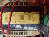
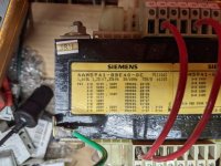
Well, I brought over (in my airline suitcase, no less) a 1.6(7.35)kva transformer which has the proper taps and is labeled for 50hz (50/60). I have hooked it up, hoping to have fixed the vampire draw problem, and am seeing the same results! I am feeding 230v 50hz single phase into the primary and pulling 120v 50hz out. The voltage is being transformed correctly. However, I'm still measuring almost 3 amps into the transformer under no load, which is about 600w. Please check my pics, but I believe I have it wired/jumpered correctly.

Pardon the mess of my temporary system. Here's how I have it hooked up. (I just put multimeter leads on the output.)
PXL_20210930_095507990.jpg

Here is closer pictures of the label:
PXL_20210930_095511469.jpg PXL_20210930_095514284.jpg

Measurements:
PXL_20210930_095559064.jpg PXL_20210930_095629055.jpg

I'm wondering if this is an actual problem or a measurement problem. Is there something peculiar about measuring the current into a transformer using a clamp meter? I ask because the system is being supplied by an off-grid solar inverter, and it is only reporting 200w of draw by the transformer, at the same moment that my Fluke is measuring 600w going from the inverter to the transformer. 200w (for an off-grid system that carefully watches draws) is still a lot 24/7 when for a device that won't be doing anything most of the time, but is less, though still significantly more than the ~1% of FLA that members here said to expect for an idling transformer.

Anyone have any insight here?
Thanks!
 
I'm the least qualified person on the site to comment, so here goes:

If you're saying that your measurements show a 600W dissipation within the transformer, then it would be getting really, really hot. Burning hot.

Do you have an IR, or better still a good contact thermometer (IR thermometers can have issues with getting good reading off metal due to emissivity)? Take some readings and let us know the dissipation only (not under load) temperature of the transformer.

I suspect it's not ridiculously hot (as you'd have noticed it), and there's something wrong with the way you're getting your 600W reading.
 
I started to write this out twice, but simplifying several lectures from an electrical engineering course into a single post without making it confusing was difficult. Some other folk have made the explanation more clearly than I was managing in this article.

The things that are specific to your installation are that the inverter sees more current than would be assumed from a 200W load, but the solar panels will only be seeing the 200W that is what makes the transformer warm. The inverter needs to be sized for the current and the solar panels are sized for the watts that the inverter is displaying. If you're lucky, the inverter can display current and power factor as well as the power and you'll be able to see how things change with different loads.
 
I'm not sure what the inverter is doing. First you do not have 600W, you do have 600VA. Some inverters put out a square wave rather than a sine wave, I'm not sure if the Fluke meter will measure square wave amps correctly. In addition if your inverted is producing square wave the transformer is designed and rated for sine wave input. Some inverters can put out a high frequency and attenuate the voltage to produce a sine wave.
You might try connecting the transformer backwards in that, disconnect the primary and connect the 120VAC secondary to your local power and then test input current on secondary side.
 
... . Is there something peculiar about measuring the current into a transformer using a clamp meter?

Oh gee. How interesting. Somebody making a current measurement with an amp-clamp. What could go wrong?

Short answer you are measuring the sum of real and reactive currents. The power you are calculating is partly real power and partly imaginary. Some of it heats the part, some does not. Inductive clamp-on meters read the SUM of reactive and imaginary currents. There's nothing wrong with your transformer. Transformers typically have some real mangetizing current but at the numbers you measure the thing would be a space heater in short order.

This topic comes up with considerable regularity. You don't need a 'true rms meter' you need one that can measure both imaginary and real power separately. Your house's wattmeter will measure only real power but you'd have to shut everything off in the house and wait a few hours to see what the real power draw is.
 
The rating of that transformer is confusing.

However, the type of ammeter is NOT the problem. The clamp-on type meter is fine, and in fact is used with meters that DO measure power factor, and separate real (power) and reactive current.

For work with inverters, a true rms meter is better, but that also is not likely to be the issue here.
 
... The clamp-on type meter is fine, and in fact is used with meters that DO measure power factor,...

Not here however. I'll leave it to you to explain to the man how to measure what he *wants* to measure, with what he HAS on hand. (and no 'first, assume a can opener'...)
 
Probably as good as anything, but not terribly useful- Power Triangle I'm going to say you probably can't measure what you want to measure with anything you're likely to own. I'd just go by how hot the transformer is. We have a step-something transformer on the wall at work and the attached device is rarely run. I've suggested turning off the power to the transformer when it's not in use because it runs about 170 degrees F all the time. You can't leave your hand on it. Nothing wrong with it, it just has fairly high losses. Good iron is expensive and nobody wants to buy an expensive transformer that's larger than you'd think it should be. Thus, they run hot. (And no, unless the waveform is distorted you don't need a true RMS meter. There's nothing wrong with clamp-on probes either. You just need a way to measure phase shift. IR thermometers are fine too, just use it on a painted area, preferably flat black.)
 
Measure the DC resistance of the 230 volt winding using a DC resistance method as in Simpson 260. Some meters measure resistance using ac which can give misleading results. Multiply the by the square of current. That will give an approximate value of the power loss due to winding resistance. There is also a loss due to eddy currents and hysteresis in the iron but these should be small.

Tom
 
Probably as good as anything, but not terribly useful- Power Triangle I'm going to say you probably can't measure what you want to measure with anything you're likely to own. I'd just go by how hot the transformer is. We have a step-something transformer on the wall at work and the attached device is rarely run. I've suggested turning off the power to the transformer when it's not in use because it runs about 170 degrees F all the time. You can't leave your hand on it. Nothing wrong with it, it just has fairly high losses. Good iron is expensive and nobody wants to buy an expensive transformer that's larger than you'd think it should be. Thus, they run hot. (And no, unless the waveform is distorted you don't need a true RMS meter. There's nothing wrong with clamp-on probes either. You just need a way to measure phase shift. IR thermometers are fine too, just use it on a painted area, preferably flat black.)

Currents in iron containing circuits typically IS distorted. Unless the clamp amp meter uses an iron vane movement, the meter will most likely be D'arsonval calibrated in RMS for mechanical meters. Flukes and similar probably report the value as True RMS.

Tom
 
Currents in iron containing circuits typically IS distorted. Unless the clamp amp meter uses an iron vane movement, the meter will most likely be D'arsonval calibrated in RMS for mechanical meters. Flukes and similar probably report the value as True RMS.

Tom


Especially if there is a bit less iron than there ought to be.... Then you get a slightly delayed distortion of the peak current, which throws off the average calculation, because that normally assumes a sine wave.

There are Fluke meters that do average, and there are Fluke meters that do true rms. And Fluke meters that do power factor and all sorts of interesting power measurements.
 
Not here however. I'll leave it to you to explain to the man how to measure what he *wants* to measure, with what he HAS on hand. (and no 'first, assume a can opener'...)

The measurement he has is fine. There is no need for fancy-dancy measurements, we already know what is going on.

If the OP does what Tdegenhart suggests, and calculates the actual power based on the measured current and the resistance of the transformer primary, he will have a very good measurement of "true power".

If the clamp-on measures the current, it is actually present, and creating a magnetic field. So that is entirely fair. There is no issue with "real" and "imaginary", because that distinction is entirely "timing" or phase. The current is in the wire either way, and will heat the transformer based mostly on the copper loss.

What the ordinary meter fails to do is to measure the corresponding voltage, for calculation of true power. It only measures one thing at a time.

But, knowing the resistance, it is a simple matter to calculate the true power dissipated (the copper loss, anyhow, which is nearly all of it) by squaring the current and multiplying by the resistance. Some iron loss will be ignored by that, but it is good enough for this problem.

If the meter is true rms, then all is fine. If it is averaging, it may be a few percent off. But that will not be an issue here.
 
I don't think the OP is concerned about Watts. He simply incorrectly converted to Watts by what the clamp on meter came up with as current and probes on the same meter the voltage. Fluke is a good brand meter, nor sure if it is True RMS or computed. The OP feels the transformer though unloaded is drawing more amps than it should be. I simply think if he were to measure the current to the transformer if connected backwards, primary open and secondary to 120VAC power line he can test the transformer. Probably can also use 120VAC to primary or 240VAC if he has it available. Again it will allow him to get current reading he can compare to the current when connected to the Inverter. If transformer is good then the output from the inverted is creating a "Vampire Draw" which I assume means more that what it should be. A simple comparison to the Amp readings will not require exact numbers. I'm thinking the output of the inverter being Square Wave or High frequency is causing the "Vampire Draw".
Also he might want to connect a known load to see if the increase in primary amps is about the equivlant (1/2 being a 2/1 ratio) Load should be resistive.
 
Measure the DC resistance of the 230 volt winding using a DC resistance method as in Simpson 260. ...
Tom

The dc resistance of the winding is probably just a couple of ohms, and a simpson meter won't do a good job. A good DVM that has at least one digit after the decimal point will be needed I think. I like Conrad's 'how hot is it' approach to life.
 
I don't think the OP is concerned about Watts. He simply incorrectly converted to Watts by what the clamp on meter came up with as current and probes on the same meter the voltage. ......................

The point of the resistive watts is to see if the actual power draw is reasonable. If it is not, then there is a suspicion that something is not exactly right with the way things are connected, with the voltages or the waveforms.

It may not be "needed" to measure that. But there is what appears to be excess current draw. Is it really "excess"?

In normal conditions, as mentioned, I'd expect a low current draw when unloaded. And it would have a very low power factor, possibly significantly less than 0.1.

Here, the actual power vs the VA will give the power factor, and if it is higher, as I think it may be, then the transformer is probably just a bit low on inductance for 50 Hz. That strange rating suggests that is so, and that the transformer is expected to act that way.

The rating is odd, but the way of explaining the hookup is odd as well.

Hee is a picture of what seems to be the same model, but with a bit clearer view of the connections for different voltages, including the connections needed to parallel the windings for lower voltages. That may be part of the issue here.

When looking at the photo, the top hookup seems to be for 440V. It is too bad the bottom numbers are not visible. If the bottom numbers are increasing left to right as it seems, it is set up for 230V secondary.

The "Verb" may likely mean to bridge the terminals indicated (verbrucke?). In that case, the one the OP pictured is set up for 220/230 input.

The physical size looks OK for 1.5 kVA or so, just based on assumed size of other things. Some smaller transformers are made less efficient electrically to save on materials. The one the OP shows carries the same number, but looks like it might have a bit less "stack".

LpsWE4H.jpg
 
I understand why watts is being measured, it's to determine if input power is OK being the transformer is unloaded and input current is quite high. But a comparison of Amperage will do the same and not need proper conversion to watts. Not sure where the photo of the transformer JTS posted is from but that label is different in appearance but the connections are the same and it is wired for 440VAC but in the OP's photo the connections for 240VAC and 120VAC are correct.
 
The 240 is correct.

The connection for 120 (meter leads) is not the way it should be to get the correct current, although it will give the correct voltage, which is what was wanted.

And it definitely looks to me that the one the OP has less "stack", despite being the same number. That could account for the current draw.

While the current itself is a useful measurement, knowing the power draw reasonably well will show if there is a higher than expected power factor, which would go along with the smaller stack. More or less of a sanity check.
 
The dc resistance of the winding is probably just a couple of ohms, and a simpson meter won't do a good job. A good DVM that has at least one digit after the decimal point will be needed I think. I like Conrad's 'how hot is it' approach to life.

I agree a 260 is not the best way but it is unlikely that the OP has a DC double bridge. I steer clear of DVM's for this type of measurement unless I know that the resistance is measured using a DC source. I have seen some really screwy values when using an AC source meter on inductive loads.
 
I've never seen an AC source meter. But that is not the only one that can have a problem.

High inductance can delay current flow, and cause very peculiar results. You may see this from the time it takes even the Simpson to "settle" to a consistent reading.


Back
Top