What's new
What's new

Another Drum Switch Wiring GE CR102B

ProSeriesRacing

Plastic
Joined
Aug 9, 2018
Hello, need help wiring for 220 and 110 voltage for Forward & reverse operation.

Confused by the diagram, which way is the lever (top or bottom) and what they call the front and rear terminals (top or side) orientation.

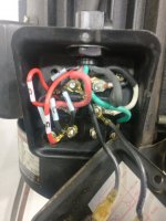
Have the 220 wiring figured out on the motor, grouping 2,3,5 together, 1,4 and 6 on individual terminal studs. Have red & 6, black & 1, white & 4 on separate studs.
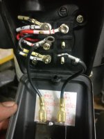
How do I connect to the switch for 220 operation?

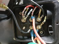
For 110-120 voltage, group 1 & 3 than 2 & 4 on individual studs and have 5 & 6 on separate studs?
Than the connection to the GE switch?

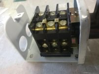
Using GE CR102B 313A switch
Here is several photos for review
 

Attachments

  • IMG_20180809_193720.jpg
    IMG_20180809_193720.jpg
    88.6 KB · Views: 909
  • IMG_20180809_193739.jpg
    IMG_20180809_193739.jpg
    83 KB · Views: 383
  • IMG_20180809_201559.jpg
    IMG_20180809_201559.jpg
    82.8 KB · Views: 390
  • IMG_20180809_202443.jpg
    IMG_20180809_202443.jpg
    85.8 KB · Views: 411
  • IMG_20180803_162225.jpg
    IMG_20180803_162225.jpg
    77.4 KB · Views: 325
Managed to figure out the 220 1ph portion of the wiring with the GE CR102B 313 switch. The motor forwards and reversing as directed.

Will try and figure out the 120 voltage 1ph operation next. :nutter::crazy:
 

Attachments

  • IMG_20180810_202959.jpg
    IMG_20180810_202959.jpg
    85.1 KB · Views: 1,372
  • IMG_20180810_203036.jpg
    IMG_20180810_203036.jpg
    89.1 KB · Views: 297
The "front" terminals would be the ones closest to the cover. The "back", the ones closest to the backplate. Your clue is the "front" ones being connected together in your pic of the wiring diagram, and the pic of the switch.

The diagram is not too helpful, ir seems to refer to an "instantly reversible 5 lead motor", Most motors do not fit that description. But it does show the switch operation.

5 and 6 are the "start winding", so those are what gets reversed in connection to reverse the motor. You need to use the switches labeled "F" and "R" for them, since they are shown to reverse for F and R.

The two shown as "F & R" are just an on/off switch, and get connected to the main (run) winding of the motor.

The start winding is a 120V winding, so for 240V it is connected across just half the motor winding. For 120V i is connected across the line.
 
FUNNY thing. I find I ot 2x as hard to explain but can do it with no fuss in about 10 min. I know I have l1,l2 & l3 coming in. once those are identified then there should b3 three wires off the motor then easy part. Then look at the switch orient it with e diagram and connect the dots. Okay so you do not have a schematic. All you need do is make center position off all there l1, l2, and l3 are not engaging he mtr wires. Left or right should take 2 mtr wires and flip them when engaging the primaries and visy versy.
like I said more difficult articulate then just do or show someone how.

Brings up a interesting topic; those can show are becoming lower in number, or so I have heard. I taught at votec school for a few year art time. I taught boot camp class, it was a VERY broad spectrum class. Really to a brief over view of machining, chemistry, math, physics etc. What I overserved was out of say 30 students, there 3-4 who really wanted to be there and learn. Rather disappointing cause this how arts die.
I worked a tool and die guy that had 30 year in the trade on me. very quiet, but I found if you just walked up him and said
" hey hot yhea ? and a bit later mentioned a problem or question you were having he was on it like flies on, I learned at least 1 thing if not more each from him, There are fewer of both hes and mes; scary in way cause one day not far off may have up our increase machining and engineering #s fast.


Back
Top