What's new
What's new

Variac to Reformat VFD Caps

Joined
Jun 9, 2008
Location
Burbank, CA
I have a couple of VFD's sitting around that I want to reformat.

Both require 3 phase input and I was wondering if a standard single phase variac (0-250VAC) would work.

Would just connecting the single phase variac to T1, and T2 terminals do the trick?

Thanks in advance.

Chuck
Burbank CA
 
The caps are DC, so no matter how you apply the input, the caps get the charge.

I start "new to me" vfds on the variac. It is informative to know at which voltage level the electronics wake up.
 
Thanks!

Thanks for the quick responses. Will use my 0-240Vac Variac. The prices on 3 phase Variacs can be up there.

Note: I think I mistyped my original question, I meant to say
I would connect the Variac to L1 and L2.

Chuck
Burbank, CA
 
Thanks for the quick responses. Will use my 0-240Vac Variac. The prices on 3 phase Variacs can be up there.

Note: I think I mistyped my original question, I meant to say
I would connect the Variac to L1 and L2.

Chuck
Burbank, CA
Yes, but again, to CalG's point, you still have not stated the voltage rating of the drives. If you have 480V drives, a 250V variac is not going to cut it.
 
On the account of voltage

I had this issue with my first 440V VFD, not having a load transformer at the time.

Variacs do output "over line voltage", Which I combined with a buck or boost to get just enough voltage to turn on a Toshiba unit. IIRC the threshold was right around 300V. It seems that the 360-440 V devices share control electronics. ;-)

I must admit that some of the "wiring" would have been regarded as "unsafe" as it was all sprawled across the work bench. But it worked, and no kittens were killed while testing. ;-)
 
Everyone who messes with electrical/electronic stuff ought to have at least one "4-way" transformer around.

They are either 4 x 120V, giving 120/240 to 120/230, or they may be 120/240 to 240/480. Probably other combos as well, but those are handy ones. Perfect for tasks like re-forming caps, etc.

I like, when possible, to put a resistor (may be a light bulb or two of the old type) in series with the VFD. 40W is a good size. In case of problems, it tends to cut down on the amount of things that get "launched".

Several, ,maybe 4, stops on the way up for 20 min or so per stop, normally is fine,
 
And you know, reforming a 460 volt cap up to 240V is still better than doing nothing and just wiring it up!
 
Probably, anyhow.

The cap will "leak" at an increasing rate as the voltage goes up on an incompletely formed one. As the "leak" goes on, it "forms" the capacitor,and the leakage drops. If you can get it up to a reasonable voltage, and then apply full volts with some resistance in series, you have a decent chance at it.

Even so, I like to get it up to 3/4 voltage anyhow, no magic calculation involved there, pretty much a "WAG".

IF you monitor leakage current, you can keep it at a reasonable leakage, and likely go up faster. That's essentially what the manufacturer does.
 
IF you monitor leakage current, you can keep it at a reasonable leakage, and likely go up faster. That's essentially what the manufacturer does.

What is leakage current, and how do you measure it? Is it the amount of current going through the cap from the variac?
 
Leakage is the current thriugh the capacitor. It's hard to measure when the cap is in a product, you can really only notice it in the area of lower voltages before the internal power supply comes on.

If the unit is one with a transformer to power the controls, you are able to more easily measure it.

You would supply DC instead of AC and measure the DC current. There will be a constant drain by bleeders, and there MAY be a drain that decreases..... over a few minutes the drain falls, then becomes steady. At that point you can increase voltage again.

Not every VFD will allow that measurement, because of internal circuitry that draws enough current that it swamps any leakage. Once the internal power supply comes on, it will swamp out leakage.
 
I have always used a 110v variac with a 1 or 2 amp fuse, then a small control relay to bump it up to 240 or 480, depending on the vfd I'm working on.

I like to use the transformer to isolate myself from the line, but mostly so I can use a smaller fuse.

I prefer to think that if I'm going to make a mistake at 480, I'm gonna stand a better chance of surviving it with a smaller fuse.
 
I have always used a 110v variac with a 1 or 2 amp fuse, then a small control relay to bump it up to 240 or 480, depending on the vfd I'm working on.

Do you mean "small control transformer"?

I was looking at a pretty hefty 120-240 control transformer in a plastic box with fuses - $45
About 5-6 different 240 V variacs (8in diameter) for about $65 - $95.
 
Last edited:
I didn't want to start another file for capacitor reforming. I'm approaching the thing from the rear end.
I connect in order: small variac, transformer, diode bridge, capacitor. This gets enough DC potential over whatever time range you like.
There is a red led indicator light hanging off to the left to show charge state. Not sure if I will make it into something decent yet.

DSC_1147.jpg

Have any of you reformers (praise the lord) used the +Bus and -Bus terminals (if available on a VFD connector) to connect a DC voltage for reforming?

Those two terminals are supposed to be used with a optional brake kit(s). In truth about this, the caps should not be charged in a bank and then assume
everything is ok. Each one should be charged and then left on a dc potential while measuring leakage current. I was thinking about doing that with this
particular drive because it is well exposed (parts wise) and I bought it for controlling small electric motors like for coil winding using a foot peddle.
 
Ideally, individual checking and re-forming is good. But it is WAY too "invasive" for standard use.

Using the bus terminals that are provided for an external brake unit should be fine.

Use of the RESISTOR terminals when there is an internal brake circuit, is NOT OK. The braking transistor gets in the way.

To prevent damaging surprises. a low current fuse in series is not a bad idea. Something around 1A would likely be a decent compromise, the internal power supply should draw less than that. You will want to be a bit careful about how fast you turn up the "juice", or the fuse may open on the surge.
 
Thanks guys.

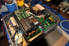
I bought this Allen-Bradley VFD for $100 and I'm planning to install my own control circuit with LCD display.
Have a graphical interface with curves for parameters, etc. I hate the led code number business for programming parameters.
All it take is removing the existing control board and installing one of my designs. Which is not that hard, just switch
six outputs at TTL or CMOS levels. The hard part (for me) is learning the feed back theory and such.

The control circuit which is dealing with a keyboard, led status display, and alphanumeric lcd.
I actuality the slim board in the center is the control.

DSC_0885.jpg

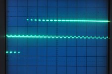
A space vector PWM waveform at 60 Hz.

DSC_0882.jpg

The vfd has this control board on top. Remove and substitute another board. That's the plan.

DSC_1148.jpg


Back
Top