jordanirvin
Plastic
- Joined
- Oct 27, 2019
Hello All,
I know this has been posted before, but this is a different motor, so I wanted to keep the replies separate, hence the new posting.
I have a very old motor, and I believe from internet sleuthing (dslreports user drjim | DSLReports, ISP Information), a Repulsion start induction
Single phase.
There is no wiring diagram on this, but the badge says, Hendricks Magneto and Eelectric Co, Indianapolis, IN. From other posts and videos, I think this is probably about a hundred years old.
Type: D20
Volts: 40
Amp: 20
KW: 0.8
RPM 1800.
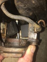
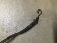
It has two massive brushes, no capacitor, and no wiring diagram, and the terminals aren't numbered in any way, so I'm just referring to the left to right. I bought it at a farm auction, and it had a single insulated wire (pictured) connected to one of the four terminals pictured here (the terminal on the right side). There was no plug on this wire--I'm not sure if this is 110V or 220V. For the four terminals, the first (large) is connected to the second (smaller) with a copper plate. The larger terminals (the first and fourth) are connected to the two brushes, and the smaller terminals go to the coil on the inside of the motor housing.
I've pulled the rotor to clean it, and have one wire on the arbor end of the motor (away from the brushes) to re-insulate. I'm in the process of cleaning and re-packing the bearings, scrubbing the dirt off of the rotor, squirrel cage, and stator.
My big question for you all is how to wire this up. I have a multi-meter, but am a complete novice at using it. I'm somewhat comfortable running a 12-3 wire to a switch and then to the motor, but that's about it. If possible, I'm looking for very clear instructions on what poles to connect to the black and white wires coming off of a switch, and if any poles should be tied together. I'll ground the motor directly to the frame.


