motion guru
Diamond
- Joined
- Dec 8, 2003
- Location
- Yacolt, WA
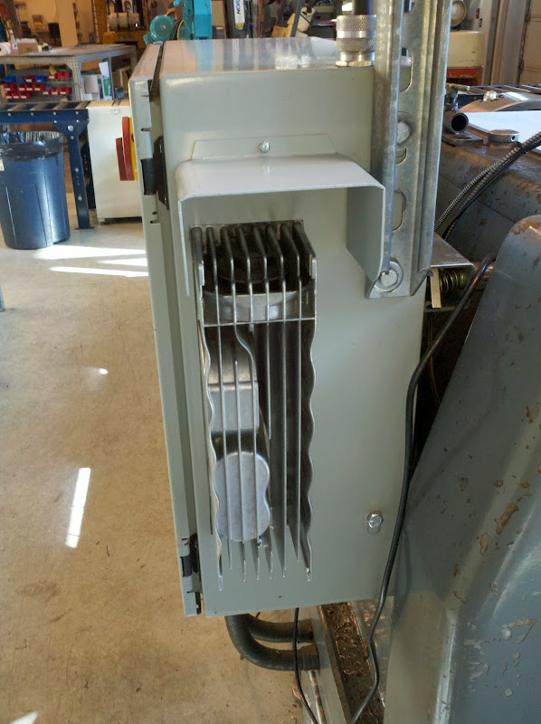
We just went through replacing the gearbox input shaft spline and hub due to the hammering that the input shaft takes every time we start / stop this lathe. It really bugs me to hear all the gears slam when you flip the lever into Forward or Reverse . . . no clutch = slam-bam on the entire geartrain every time. Stomping on the brake essentially does the same thing.
Next step is to put a VFD on the lathe. The lathe really only has 3 switches on it related to the spindle.
Forward - obviously closes with the lever in forward
Reverse - closes with the lever in reverse
Brake - drops out spindle motor starter coil power when the brake pedal is pressed.
I decided that I want the drive to Dynamically Brake the spindle to a stop whenever the FWD/REV lever is put into Neutral or when the operator wants to do a direct reversal. But that if someone steps on the brake pedal, just disable the drive and let the brake do its thing.
I came up with the following simple control schematic to make this happen. I could have done this with fewer relays, but this allows quick / easy trouble shooting in the event a switch goes bad.
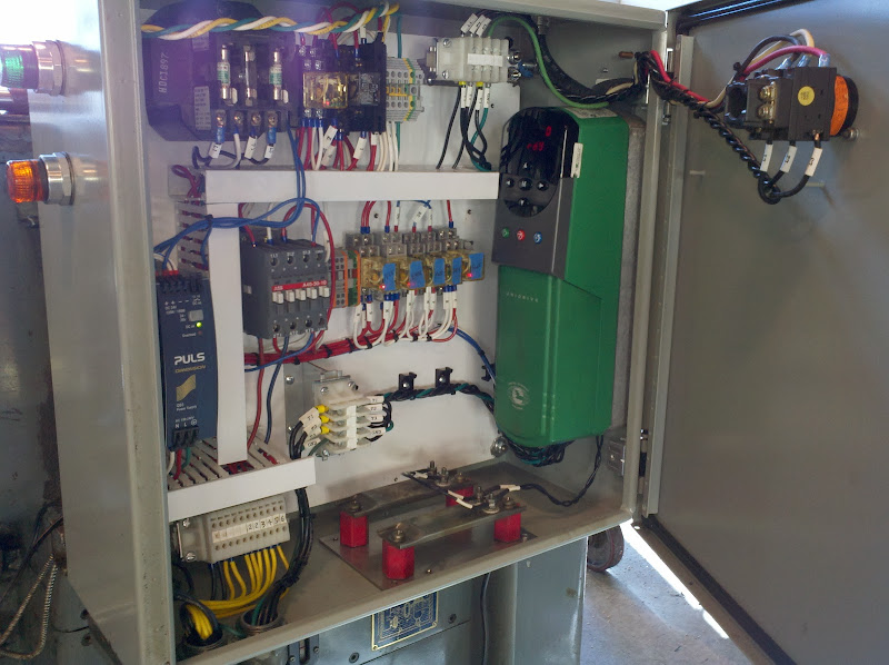
I have a 24VDC power supply already in the control cabinet - so I'll run IDEC Ice Cube Relays with LED indication. (Similar to these)
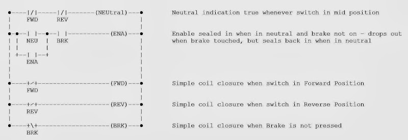
I'll use 2 pole relays and FWD, REV, ENA dry contacts will go directly to the drive. I'll eventually put a speed pot on it as well and likely a rate counter on the spindle shaft to read RPM directly and put the display up near the DRO. Updates as I get it installed and working.
Next step is to put a VFD on the lathe. The lathe really only has 3 switches on it related to the spindle.
Forward - obviously closes with the lever in forward
Reverse - closes with the lever in reverse
Brake - drops out spindle motor starter coil power when the brake pedal is pressed.
I decided that I want the drive to Dynamically Brake the spindle to a stop whenever the FWD/REV lever is put into Neutral or when the operator wants to do a direct reversal. But that if someone steps on the brake pedal, just disable the drive and let the brake do its thing.
I came up with the following simple control schematic to make this happen. I could have done this with fewer relays, but this allows quick / easy trouble shooting in the event a switch goes bad.
I have a 24VDC power supply already in the control cabinet - so I'll run IDEC Ice Cube Relays with LED indication. (Similar to these)
I'll use 2 pole relays and FWD, REV, ENA dry contacts will go directly to the drive. I'll eventually put a speed pot on it as well and likely a rate counter on the spindle shaft to read RPM directly and put the display up near the DRO. Updates as I get it installed and working.


")