What's new
What's new

A VFD for my Bridgeport

Johnny V

Cast Iron
Joined
Jan 19, 2005
Location
Mentor, Ohio
Finally bought a VFD for my 1hp Bridgeport. For years, yes that's right, YEARS, I've been having to use my lathe as a rotary converter to start my mill because it would constantly "single phase" when I would attempt to start it. First I thought it was the drum switch, so I replaced it with a reversing mag starter and still had the same problem. So after reading through the posts on this and other forums I decided it was time, and am I glad I did. The unit is a TECO FM50 (maybe not the best, but it works for my situation) that is in an Eldon enclosure, and uses a remote push button station with momentary contact switches (Stop, Start, Forward/Reverse, and a 10K Potentiometer). I added Vents to the top of the enclosure to aid in cooling and a Plexiglass window to view the Frequency reading. When funds allow, I'll be changing my grinder over to a VFD, til then, run the lathe. Attached are some pictures.
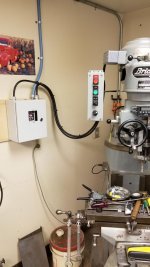
300.jpg 200.jpg 100.jpg
 
Nice neat looking job. Looks like good work - professional like.

I have a few questions, if you don't mind.

- Why do you go through the terminal blocks you added inside the box, instead of simply hooking the wires directly to the VFD?

- It's hard to tell from the pictures, but it looks like you used 14ga wire coming in the box, or is that 12?

- How did you hang the remote box (the one with the start/stop, fwd/rev)? I'm interested in what you used for a bracket and how you attached the bracket.
 
I have been considering doing the same thing with my BP. Since it isn't a variable speed. Nice box for it, I hadn't planned anything quite so extensive.
 
FYI, it is not a good idea to tie the motor cable and control cable together, as you can get false signaling from induction. The low level signaling for the run/stop/direction and speed pot typically use much smaller gauge wire, I normally like to use shielded 18-22 AWG wire cabling and use direct connects to the VFD. On loner runs between the VFD and motor, I also uses shielded motor cable. Typical connection of the shields is at the VFD end only. Good to use a star/bus ground as you have done. I like to put a power disconnect at my VFD enclosure along with fusing/breaker if not on a dedicated circuit. Below id a recent system where I put the mill controls in a pod that attached to the knee and the E-Stop, tach and speed pot on the head. It also uses a ring LED spindle light and various sensors to detect back gear and for auto reverse.

PM949 Control System.jpg
 
Nice neat looking job. Looks like good work - professional like.

I have a few questions, if you don't mind.

- Why do you go through the terminal blocks you added inside the box, instead of simply hooking the wires directly to the VFD?

- It's hard to tell from the pictures, but it looks like you used 14ga wire coming in the box, or is that 12?

- How did you hang the remote box (the one with the start/stop, fwd/rev)? I'm interested in what you used for a bracket and how you attached the bracket.

I added the terminal strips for ease of installation (fat fingers)

Power into the box is 12ga and control wiring is 18ga, 8 conductor

Bracket uses 2 of the belt housing bolts and was just some 1/8" x 2" flat stock I had laying around that I welded together.
Push Button Bracket.jpg
Got the Idea from Jake Belk on YouTube (3:36 on video)

I have been considering doing the same thing with my BP. Since it isn't a variable speed. Nice box for it, I hadn't planned anything quite so extensive.

The whole setup cost less that $200.00 and makes life on the mill a whole lot easier.
 
I used the same drive. My first VFD.
Learned quite a bit.
So far so good. I don't do any heavy
milling so will not tax the drive.
I power it up every so often as I have
read about some people having trouble with
caps that have set for long periods.
olf20 / Bob


Back
Top