What's new
What's new

VFD with NO speed control? But only to get 3 phase...

Gumbydammit

Plastic
Joined
Mar 25, 2021
I have a bench grinder that is 3 phase and I want to drive it with a vfd. (1 hp unit, 240V) I don't want to use any of the variable speed functions, just as a way to get the third leg like you would with a rotary phase converter.

Here is my question. Do I just set all the frequencies to 60hz (USA) so it acts like regular power? I'm just not sure what to do with all the braking and acceleration. Is it necessary?

I am going to experiment, but I thought someone here may have some insight. I have googled the heck out of it and watched a ton of videos, but oddly enough, no one seems to deal with this simplest of cases.

Thanks in advance.

H
 
Unless you significantly oversize the VFD, you need to use the acceleration. Otherwise, you will overcurrent the VFD, and depending on how it is set up, it may just stop and refuse to start the motor.

Some will limit current and keep running, but why depend on that when you can set an accel which will start the grinder?
 
Quick follow up. I checked and rechecked the parameters on the VFD. I had it at 240v, 60 hz, and set the rampup to 1000, thinking it was in miliseconds... lol it was not... it was seconds... It was funny watching it try to ramp up that slowly.. So I fixed the ramp up time and the motor got incredibly hot in no time flat. The motor is dual voltage, and I thought I would try to rewire it out of delta and in into wye.

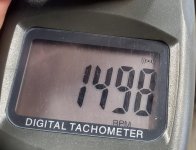
I found the polarity of all the coils using the bump method, and set it up in wye. I have also ordered a couple line filters knowing it's an old motor, It says when you wire it in wye, that it is supposed to be for 480v. But after wiring it that way, it was running fine, but with less rpms. I upped the frequency to 100hz, and now, the rpms are right where I want them to be. I am being extremely cautious until I get the filters, but I ran it for about five minutes this morning and it barely got warm. and my little digital tach said 1800 rpm, just like the tag on the motor. And it appears to have a ton of power. I'm currently very happy.

This has been frustrating to consolidate any info on this device, so I will probably post progress in case it helps someone else.

Thanks everyone for the input. This is a great forum.

Peace,
Gumby
 
Run the bench grinder motor as a RPC motor. Use a start capacitor. I know I could do that with any RPC I have ever guilt.
 
Yes the motor will get hot with ramp time set to 1000 seconds, because the default boost volts are too high. Basically for the first 20% of the ramp time, the actual current flowing in the windings are higher than needed, most vfds are pretty dumb and don't deliver a proper sinewave below 6hz either.

A 480v motor wired for delta is going to want 277volts, a 240 vfd is a good fit and the motor will still develop rated torque up to about 50hz. Above this it can deliver rated torque but amps and heat will be higher than nameplate values.

Could it be you had the motor wired wrong?
Because your description is strongly suggesting it still is:
You should not run the vfd at 100hz even if the motor is running well below 100hz due to the risk it may speed up and blow up.
 
Yes the motor will get hot with ramp time set to 1000 seconds, because the default boost volts are too high. Basically for the first 20% of the ramp time, the actual current flowing in the windings are higher than needed, most vfds are pretty dumb and don't deliver a proper sinewave below 6hz either.

It did not get hot from that. I saw that in the first five seconds of the ramp, and immediately stopped it. I just talked about it becaue I thought is was funny to picture a 1000 second ramp. lol

A 480v motor wired for delta is going to want 277volts, a 240 vfd is a good fit and the motor will still develop rated torque up to about 50hz. Above this it can deliver rated torque but amps and heat will be higher than nameplate values.

The motor is an OLD black and decker motor and there are not wiring charts on it anywhere. So when I got it it was wired for delta. But I'm telling you with all the same values I'm using, it got so hot in about twenty seconds, there was a strong smell and after shutting it down, wisps of smoke. I thought I may have cooked it, but I think it was just dust cooking.

I decided to try and see what happened if I wired it in wye and still used 240. So I did that and it started to work great. The only issue I could see was that the rpms were too low at 60hz. I was only getting about 900. So I upped the hz to 100 and the rpms went to the rated speed.

Yesterday, I wanted to be careful, so I let the motor run for about ten seconds, then sit, then twenty, then sit, then 30, lather rinse repeat. I started to go in five minute intervals until I had the motor running non-stop for 30 minutes. It was only warm to the touch. (And I'm talking the coil itself, not the housing. (There is a hole in the bottom of the motor inside the base and after removing the power, I could actually touch the coil to see if it was hot.) I'll start posting pics today. I've been working, and not able to get that done yet.


The only issue I had was that after identifying the coils and finding the polarity, the motor ran backwards, but I flipped two of the leads and that went away.

Anyway, I'm excited. I often have to pass on great deals for machinery because 3 phase intimidates me, but not so much anymore. I sense some great American made sturdy equipment in my future.

Thanks,
Gumby
 
my old Deckel S1 tool grinder has 2 speed 3 phase motor, it isn't normal and high speed, it is low and normal, so if you connected to the low speed (more poles per revolution) and ran it at twice the frequency - you'll get normal speed but increased torque

running at very low frequencies makes it hot because the windings get magnetically over saturated and then act as a simple resistor (vfd should have some sort of settings to prevent this), with not a lot of resistance, so all that current gets converted into heat, hence the motor got hot quickly

since these motors usually have the cooling air impeller directly on the shaft - they MUST not run at low speeds for long periods of time, there won't be enough air circulation and the thing will overheat, motors for these applications have a dedicated fan
 
Okay, more updates.

I discovered the reference I had, listed the wye and delta description backwards for describing which was for high speed/voltage in a two speed two voltage motor. (My new reference said wye/low, delta/high)

The other references I found said delta was for the lower voltage/speed. Here is the motor I have been working on...
20220119_150757.jpg

So with the new information, I went back to the beginning. I bought a 5 dollar analog multimeter so I could follow a tutorial I saw about winding polarity. Here is what it said.

Kick_Method_01.jpg

It was a little hard for me to follow in text alone, but I got it figured out. So after getting the coils labeled, I moved the leads forward and tested the first set that were connected to the battery to see how that one "kicked" That one kicked backwards, so that leads me to assume one set of leads needs to have the reverse polarity? Does anyone know if that is correct? Well, regardless, I got it all hooked up in wye and set the settings to the specs on the faceplate. (220V and 50hz). Fired it up and poof the motor went up in smoke... Ha!... Just kidding. it began to work well and the rpms now matched the faceplate without messing with the frequency of the drive.

Here is the image of the final working wiring. (ignore the ugly tape, it's only temporary to get the testing done.)
20220122_124710.jpg

20220122_131012.jpg

20220122_132532.jpg

You can see that I labeled the raw polarity on the windings in red and black, but using the "Kick" method, it made me have to reverse one set of leads. So I hope I have it worked out now. I ran it for quite a while to make sure it did not get hot, and all seems well. I am still waiting on the output filter, I'll add that in for insurance when it gets in on the output side.

Again, I hope this helps someone else in the same confusion I was in trying to do this for the first time. Here is the one question I still have for a wiring guru that may read this. Why oh why is the lower voltage listed as 50hz?? That confuses me. Is that some kind of old standard?

Well, that's all for now.
Gumby
 
The wye for high voltage is actually true.

With the delta connection, you would have (for instance) a 230V winding right across the L-L voltage. If that is 230, you are fine.

With the wye connection, you instead have the 230V winding from line to neutral. The line-to-line capability is then 1.73 x the line to neutral, or, in the example, 400V.

(In the US, that is used to get standard 120V line-to-neutral from a 208 V L-L 3 phase circuit)

Wye is thus for the higher voltage.

The 50 Hz vs 60 Hz is independent of the voltage in this case. The motor is rated 220/440, and rated 50/60 Hz FOR EITHER VOLTAGE.
 
Ugh.. I thought I was closing in, but these responses are both good, and both equally confusing to a noob.

That is really interesting info that the motor is rated at both voltages and both frequencies.

With the kick method worked out, I will go try delta and see what that gives me. Since I am outputting 220v and not 440v.

Thank you for the input, even if I am not super quick on the info uptake. For example... I read.. " The line-to-line capability is then 1.73 x the line to neutral, or, in the example, 400V. " and what I understood of it was stuff stuff stuff 1.73... stuff stuff 400v..... which sounds bad.

The other thing that confuses me is the line- to neutral reference. I am not technically using neutral with three hots, am I? That just leads to more confusion... Gah! lol.. brain hurty.

(Here is the verbage from that kick tutorial...) "Now that you have identified the the T leads, determine from the name plate if this a dual voltage motor or not.
If it is dual voltage, tie T4, T5, and T6 together for the lower voltage.[wye or star]
Tie T1 to T6, T2 to T4, and T3 to T5 for the higher voltage.[delta]
If the motor is a single voltage, connect T4,T5,and T6 together and insulate. Line on T1-T2-T3."

So that is wrong? The internet is a crazy place... ask ten questions, get eleven answers... Thanks for helping me set this straight.

I'll be back, and thanks again...

Gumby
 
Wait a minute..

I think I just had an epiphany. Is the 440v setup, still coming from my 220v input, but from the way I wired it as wye and not delta??

I thought 440v was a different kind of power source, not a winding configuration. Is that accurate, or am I off base again?

Gumby
 
Ugh..


"Now that you have identified the the T leads, determine from the name plate if this a dual voltage motor or not.
If it is dual voltage, tie T4, T5, and T6 together for the lower voltage.[wye or star] Line on T1-T2-T3
Tie T1 to T6, T2 to T4, and T3 to T5 for the higher voltage.[delta] Line on T1-T2-T3
If the motor is a single voltage, connect T4,T5,and T6 together and insulate. Line on T1-T2-T3."


Gumby
This is correct if you have a motor with 6 leads and the higher voltage is 1.73 x lower voltage Very common here Not so much in the US
Here the motors are 220/380 volts Not 220/440 So perhaps your motor is 220volts 50Hz 1500RPM OR 440volts 60Hz 1800RPM

Just to be sure I added the red

Peter
 
This is a straightforward three phase motor able to be connected in delta for 220 volts input and wye for 440 volts input.

If you put a 220 volt VFD onto a motor connected in wye it will run just fine but power will be reduced to about 2/3 rds rated power. Here is why.

Delta puts single windings across the phase connections and wye puts two windings in series across the phase connections so either way the voltage across a winding is the same.

The torque of a motor is defined by the current flowing in the windings. Maximum torque occurs at the rated current flow.

A spinning motor produces a back EMF opposing the source voltage that increases in with RPM. The faster a motor turns the greater the back EMF and the lower the current. The actual voltage driving the current through each winding is the difference between back EMF and applied voltage.

Things basically come into balance to give maximum torque at the rated rpm for a motor running on the fixed frequency.

An induction motor can only run at a stable speed fairly close to 60 x (line frequency divided by number of poles).

A VFD varies both applied voltage and frequency so if you connect a 220 volt VFD to a wye connected motor it is still able to drive the rated current through the windings at lower speeds but the highest speed for which back EMF is low enough for the rated current to be driven by the VFD is lower.

For a 50 Hz motor the maximum frequency at which a 220 volt VFD can drive the rated current through the windings of a wye connected motor is around 29 Hz at which a 1,400 rpm motor will be running at about 1,000 rpm.

As full rated current is flowing the motor develops rated torque and approximately 2/3 rd of its rated power. Below 29 Hz the performance is identical for both a 220 volt output VFD and a 440 volt output VFD when varying the speed.

Above 29 hz the 220 volt VFD will drive the motor at a constant power of about 2/3 rd rated power whilst the 440 volt VFD reaches full power at 50 hz before going into constant power mode.

Hope that helps

Clive
 
The motor plate means......This motor can be used in the US with it's 60 hertz electric grid or in Europe with their 50 hertz grid.

It can be used in a commercial/warehouse building with an incoming 480v. service or a more typical house incoming 220v. service.

The tag just means the motor can be used in a variety of circumstances. The voltage and hertz rating have nothing to do with each other. You can have 440v or 220v at 60 htz or either voltage can be at 50htz if you are in Europe.
 
......................

I thought 440v was a different kind of power source, not a winding configuration. Is that accurate, or am I off base again?

Gumby

You can have 3 phase at any voltage, but there are standard voltages in the US and slightly different ones in europe etc.

You can have SINGLE phase at any voltage, also. Voltage and number of phases have no definite relation, except for whatever the local standard ones are.

So 440V is just a voltage, might be 3 phase (that's common in the US), or possibly even single phase.

Three phase is the only type circuit associated with a choice of wye or delta. That is a "configuration", and within that there may be configurations of a motor for two (or more) voltages.

Single phase and three phase motors can be made for any voltage. It is most common in the US to have single phase at 120V or 240V, but there is nothing stopping a motor from using 480V single phase. I've used such motors.


Motor voltage:

Motors are designed for a certain voltage per turn of wire inside. The voltage depends on the design of motor.

For any particular motor, the winding configuration for a given voltage is set up to give the right number of turns to handle that voltage. The dataplate typically shows what those are.

When one voltage is double the other one, you need twice the number of turns to handle the higher voltage. To do both voltages, it is usual to have two sets of coils. For the higher voltage, the two sets are in series, so current goes through a coil in set one and the corresponding coil in set two.

For the lower voltage, the coils are in parallel, so half the total current goes through a coil of set one, and the other half goes separately through the corresponding coil in set 2. (Notice that the total current is now double what it was at the higher voltage, just what you expect to get the same power.)

Wye and delta:

A 3 phase motor wired in "wye", aka "star", has each coil wired from one of the three wires to a "neutral point". But that neutral point is rarely if ever connected to a neutral wire. It is a "virtual" neutral, and will have "approximately" the voltage of a real neutral. It works fine even so.

Delta has a coil between 2 of the three wires, call them the "first" and "second". Another is between the second and third, and the last coil is between the third and the first.

In delta, the coils see the nominal line voltage, which is what is between wires.

In wye, the coils are between each of the 3 wires, and a neutral point. Because there are TWO coils in series between any two wires, each coil "sees" less than the full voltage between the wires. Because of the phasing of the voltages in 3 phase (120 degrees apart), they do not each "see" half, they actually "see" about 58% of the voltage between the wires.

So when wired in wye, a coil that is good for 220 volts directly across it, can be used in a 3 phase circuit at 1 / 0.58, or 1.73 times the voltage, which is 380V.

For 220V delta, that comes out to 380V in wye. For 230V, it is 400V, and for 240V it is 415V. That is why those voltages are associated with 3 phase in delta and wye.

Maybe that helps. This stuff is just basic to 3 phase, and you kind of need to automatically think of it in order to understand connections.

Frequency :

The US uses 60 Hz, most (but not all) the rest of the world uses 50 Hz. The frequency affects the usable voltage of a motor.

A motor that is good for 480V at 60 Hz, is good for 5/6 of that voltage at 50 Hz, which is 400V, and will also run at 5/6 the rpm.

And, a motor good for 400V at 50 Hz, is good for 6/5 of that voltage at 60 Hz which is 480V (it will also run at 6/5 of the speed, and the power rating may change a bit).

Some are made to take either frequency at the rated voltage. The motor above is made that way. They still change speed with frequency, though.


Back
Top