What's new
What's new

VFD Wiring to existing Control panel Help

Awleaphart

Aluminum
Joined
Mar 16, 2019
Hello,
Start off I have wired up my first VFD to a Bridgeport mill and everything went great.I am using the existing drum switch sending the 5 volts to the rev and forward places on the VFD. I"m not running 240 volts to the drum switch.( Ask Power VFD)
Now I'm about to finish wiring up my second VFD (Huanyang Model GT-7R5G-2) on a used Lathe I bought that already has a control panel. (Lansing P15)
I'm wanting to use the lathe controls that are already there and don't know where to wire up or how to make the VFD sent power to the Lathe motor by using the Lathes Start and stop controls. My lathe has a motor start Forward,Motor start REV. and one stop. 3 push buttons. I have attached a picture of the inside of the control panel.
Any direction would be helpful.
Thanks
A Leaphart
ELE. Lathe.jpg
 
disconnect all the motor power leads from the FWD and REV contactors and instead, use them to make your appropriate switch closures to the logic buss of the VFD. You must have mag coils that will work on your available voltage though. My lathe used 120 volt coils. I had a 'pilot' switch on the front of the lathe that when swtiched, closed a pilot mag and gave power to the FWD and REV mags. When the apron mounted lever was moved up, to turn the lathe on, it closed the FWD mag which closed the circuit to the logic buss on the VFD that commanded a FWD motor rotation. Same deal for REV and JOG.

Clear as mud...just use the two mags as big switches, just like the drum switch on your mill.

As an aside, the brand drive you have selected for your lathe is on the blacklist of this site..they aren't spoken highly of.

Stuart
 
Thanks Stuart.
I think I'm picking up what you putting down. I need to look and see what the voltage is on the mag switches that are there. I hate to ask a stupid question but the machine was running on 3 phase power before with no VFD or Phase convert-would that make the mag switch 240 volt 3 Phase? I need to take the cover off and see if they have any information on them.
A Leaphart

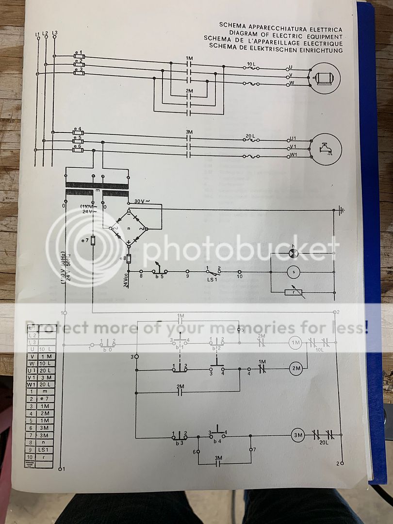
On the top left there is a transformer(stepdown?)and 2 little fuses and a rectifier, check if the contactors are DC?
 
As jmaks points out, there is a transformer in one of the pictures and I would bet it maybe has a 120 volt secondary, for both the mag coils and any indicator lights on the panel of the lathe.

Take a look and let us know..good luck.

Stuart
 
If it was me I would take the time to wire it properly, I would completely remove the fed/rev contactors and wire the control switches to the appropriate terminals on the VFD.
Using the contactors as a switch is easy, and will work, but it’s a bit crude and the contacts often are fairly beat up from years of arcing- they can be cleaned with a fine file or burnish tool if they are not too bad.
I don’t think you were, but never place the fwd/rev contactors downstream of the VFD output, The VFD won’t like losing its load suddenly


Sent from my iPhone using Tapatalk Pro
 
Well it certainly appears your control voltage is 120 volts. There are a few good reasons to use the existing mags as contact closures for your drive..the most important is that they 'latch' and that feature won't be inherent on your VFD without extra monkey motion. It allows you true 3-wire momentary control from the factory buttons, etc on your lathe. Another plus to using them is bypassing the chore of wiring and threading new circuitry through all the little tunnels and such in the structure of your lathe.

A single VFD will not be able to power your coolant AND the main motor so that's something to think about. There are some strange sounding call-outs on the wiring diagram so it would be helpful to see the actual control panel and apron levers if it has them and maybe a make of the machine too.

Once you verify coil voltage and decide to go this route, you'll find it much less intimidating once you strip all the fuses and unnecessary wiring out of the enclosure. The job looks much simpler with all the 'detritus' removed.

Stuart
 
Unclear from the schematic, looks like it is indicated the input voltage is (110VAC) and output is 24VAC for the contactors.

If you have a voltmeter you can probe the voltages. Voltages also should be indicated on the transformer. You can strip out the high voltage (black) wires to the Forward and Reverse contactors (remove the overload relay) and use a set of the contactor contacts (like L1 to T1) to control the low voltage VFD input for the direction, but in the case that the contacts have been used, they do poorly to conduct the low voltage signals (tried that in the past and didn't work). So as a minimum the contactor points need to be dressed if possible, or the contactors replaced. You can inexpensive WEG mini-contractors (24VAC or whatever the voltage may be) in the same configuration. Check Automation Direct, they are like $18. I have done a lot of basic conversions in this fashion, but not something I endorse when I build systems for others. All of this takes some basic understanding of electricity and rewiring.
 
I will post more pictures of the front of the Lathe later today. Its a Lasning P15 made in Italy. 5HP motor. If I remember correctly. On the front you have a turn switch for power the push buttons. You have a forward push button and a rev push button. When you push the forward button I'm thinking the motor would run but the spindle didn't run until you pull the apron lever down or push up. It seams to be a step down transformer to me. stepping the 220 to 110 and 30v. On the electrical plan there Items on it I don't see. They must be on the inside of the machine.
Thanks
A Leaphart
 
Ok.
I see 220V coming into the step down transformer. Out the bottom of the transformer I see 110v and 24/30 alternating volts. The 30 A-Volts going through rectifier to change it to 24 direct volts. (Correct me If I'm wrong.)
What I don't understand is what does it mean when there is 110v and 24v on the same line like the line from 0 to 1 which come out of the transformer on the left side?
Thanks
A Leaphart
 
To my very untrained eyeball that looks good so far. If that control is actually going to be used it should have primary and secondary protection. The VFD will need some line side circuit protection as well.

Did you verify that the coil voltage was indeed 120 volts?

Stuart
 
Yes it is 120v. I Ohmed it out the 110v at the bottom of the transformer. Traced it back to the contractors. There are 4 wires coming out of the bottom of the transformer. Two are for the 30v and the other two are 110v. Its labeled on the transformer also. Ones I run 220v to the top of the trans Im going to check it again.
A Leaphart
 
Kool. It appears the twist knob is the master for control voltage which would use a small mag of its own. Are the panel buttons for motor rotation only 'JOG' buttons? The center button between the two rotation buttons is RED and seems to indicate OFF which could mean the rotation buttons are not JOG but maintained.

I see an apron mounted FWD/REV lever..I think! This would be a maintained switch..but why have the two on the panel, unless they're JOG buttons. If they're JOG buttons, why the RED colored button which typically means OFF?

Is there a foot brake..a mechanical foot brake?

A mechanical foot brake usually has a switch the kills the main motor and requires the operator to center the apron lever to reset the mag before he can start the lathe again. This prevents surprise starts on powering up after application of the foot brake.

Stuart
 
Rereading some of the posts and looking at pictures of Lansing lathes answers some of my silly questions. The control buttons are forward and reverse of the main motor and it's a clutched machine. There is no foot brake in the conventional sense, but that apron handle on the left could be a hand brake..maybe?

I'm starting to look like Thermite..asking and answering my own questions and babbling on!:)

Stuart
 
Thanks Stuart,

Yes, you are correct. It seems to be a clutch machine but on the electrical diagram it does show a brake. Now, how does the brake work, I have no clue. The twist knob at the very top, on the front of the machine, per the manual is the brake. Switched to the left it has a #0 and to the right it has a #1. The apron handle, when pulled down, the shaft that is hooked to it going to the gear box moves with it. When the apron handle is pulled up the shaft moves also. At the bottom of the apron handle there is a notch, if you pull the apron handle toward the tail stock then pull it up or down the shaft going into the gear box does not move with it. The purpose of this, I am not sure.....

Today I unhooked all main main power from the three motor starter contactors and fuses. I ran 220V to the two fuses like I had on the drawing to the 220V side of the transformer. I checked the voltage on the bottom of the transformer. I am getting 125V on the right and 33V on the left side, so yes the contactors are 125V. Now the contactors are working with the push buttons on the front of the machine. Next step is to wire the motor to the VFD and try to get the settings correct with the wires for the forward and reverse.

Thanks,
ALeaphart


Back
Top