What's new
What's new

Wiring AC Tech VFD to Bridgeport- need some help/wired but not working

RPMWFO

Plastic
Joined
Jun 5, 2009
Location
COLO
I bought a used Bridgeport that was retrofitted with an Acer E-mill variable speed head and Toshiba S7 drive. It was originally setup for 480V 3ph. I replaced the Toshiba drive with a AC Tech SMVector 3 HP 240V 1ph VFD.

I am not the sharpest person electrically. I wired the drive up based on looking at the existing Acer wiring diagram and reading the AC Tech manual.

Good news- I can run the motor and control it from the drive locally. Bad news-I am not able to run the mill from the vfd terminal strip that I have wired to the control panel of the mill:3 position switch(fwd, rev, stop), spindle brake(has limit switch), e-stop, speed pot.

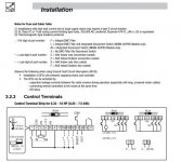
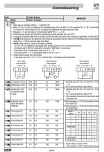
I've attached a marked up wiring diagram showing how I have the mill head control panel wired to VFD. The lower right hand corner of the diagram is the terminal strip on the VFD. I also attached the ACTech info for the terminal connections and descriptions. I have the entire manual if someone wants me to email it to them.

Can someone sanity check how I have the controls wired to the VFD? Any with experience with the AC tech VFD's that can give some programming advice? I have been banging my head against the wall trying to figure out how to get this thing running.

Thanks in advance for all the help.
 

Attachments

  • ACTECH_BP.jpg
    ACTECH_BP.jpg
    46.6 KB · Views: 10,398
  • ACSMV_Terminal.jpg
    ACSMV_Terminal.jpg
    42.7 KB · Views: 2,824
  • ACSMV_Termnal Descriptions.jpg
    ACSMV_Termnal Descriptions.jpg
    58.8 KB · Views: 2,360
  • ACSMV_CtrlCir.jpg
    ACSMV_CtrlCir.jpg
    87 KB · Views: 3,386
Just a quick blurb...

Usually there are a few interlocked control settings. You can do x, if you set y to 1, kind of a deal. If you are trying to use control parameters for a 2 wire control with a 3 wire control set up, there will be problems.

Check if you have all the settings correct (for the type of control wiring you are using, 2 or 3 wire etc) These drives are preset for a dirt simple test start up. They need remote terminal control enabled, Fwd Rvs enabled, all in the vfd settings menu side...

You have to get a pad of paper and write down any applicable settings as you go through manual... Some settings override others.... You might have to pick a slightly different control setup, to get the settings to do what you want, with your particular VFD.

It takes a reread of the manual, 2 or 3 times, to get the interactions down pat. Many of the advanced settings (braking, ramp up/down), should be ignored until machine can do the basic start stop reverse and remote speed control is working.

I did not write down the control settings when I put an AC Tech drive on my mill, must have been fairly basic...

1,2,4,5,6,13a are the only control terminals I have hooked up on my AC Tech TCF series drive. I have remote Fwd Off Rvs, and speed control working.
 
I’ve set up a number of AC Tech drives; Bridgeport, Lathes, Drill Presses, Grinders. The first one took a while (endless hours) the rest about 20 minutes apiece.

Your setup manual and drive are a lot more complicated than mine … a lot more capability but with more complexity.

A bit of valuable info I picked up from this site was to break down the first installation and to build one step at a time. This helps determine what impact each change has on the system.

If you’re at least running from the drive itself than that aspect is probably OK for now.

IMO I would disconnect all but the most basic wiring for the remote and then get the remote functioning. Begin with a basic function like speed control or forward /reverse. Once that is OK move on to the next etc…

There is a parameter that needs to be set to tell the remote to function and others tied to that as to what is to function and how…you’ll need to look for those related parameters on your parameter list.

One of the first things I do now when setting up the parameters on a drive is to reset the password to none (000)…it makes setup much less cumbersome.

I keep track of parameters for all the machines on an Excel spread sheet… with notes to myself as to why I made the changes.…

Now that they are set up I cannot function without VFD…they make machine control so much easier…

Joe
 
I'm a bit rusty but will give it a shot...used to work at AC Tech.

Out of the box, the VFD is configured for start/stop and speed control from the keypad. To change that, some parameters need to be changed.

Let's start with start/stop control. This is determined by parameter P100 (Start Control Source). If you only want start/stop control via the terminal strip, then set P100 = 1 (Terminal Strip).

If you want to be able to switch start/stop control between the keypad and terminal strip, then set P100 = 4 (Terminal Strip or Local Keypad). In order to switch between the two control modes, you will need to wire a selector switch to one of the TB-13 terminals, and properly program that terminal. For example, if you choose TB-13C for this function, you would wire the switch across TB-4 and TB-13C, and you would set parameter P123 = 8 (Control Select).

When in Terminal Strip control, there are a few different start/stop and fwd/rev configurations available, as you can see in the Notes section under parameters P121-123. Wire and program the TB-13 inputs to match your scheme.

You will also need to make sure you set parameter P112 (Rotation) = 1 (Forward & Reverse) to allow reverse direction.

Next up is speed control. Like start/stop control, speed control can also be configured for keypad only, terminal strip only, or both.

If you only want to use a speed pot to control speed, then the easiest way to do this is to set parameter P101 (Standard Reference Source) = 1 (0-10VDC). This parameter sets the speed reference that will be active if no other reference is selected.

If you want to be able to switch speed control between the keypad and a speed pot, then leave P101 = 0 (Keypad), and set one of the TB-13 inputs (P121-123) = 1 (0-10VDC) and wire a selector switch between TB-4 and that TB-13.

Keep in mind that there are only (3) programmable TB-13 inputs, so the functionality may be limited. For example, if you are using TB-13A for Start Fwd, TB-13B for Start Rev, and TB-13C to switch between Keypad and Terminal Strip start/stop control, then there are no inputs left to be able to switch between 2 speed control methods.

Hope this helps.

I have stepped through the parameters. I set the p100 to terminal strip control. P101 to 1(0-10VDC). P112 rotation set to 1(fwd and rev). P121=11(start fwd), P122=12(start rev).

I looked at my wiring with a meter. I realized that I had to swap the control wire I had on 13C to 1 on the terminal strip. My start forward/start reverse circuit checks out now with the multimeter. I removed the spindle brake and e-stop from the wiring for right now. I also removed the speed meter from the wiring. Only thing wired in is the speed pot and the 3 position switch(fwd, rev, stop).

I believe I have the speed pot wired in correctly.

When I press Run on the drive it returns ERR message. I am still at a loss. Any ideas?
 
I'll be calling AC Tech in the morning, but I am hoping I am just overlooking something simple.
 
Was looking through the manual again and saw in Section 5.2 that if you hold the Mode button down it will tell you how the VFD is configured...had forgotten about this. In your case, I believe the display should read "t_S_EU"...t = Terminal Strip control, S = Speed mode, and EU = 0-10VDC speed reference.
 
Was looking through the manual again and saw in Section 5.2 that if you hold the Mode button down it will tell you how the VFD is configured...had forgotten about this. In your case, I believe the display should read "t_S_EU"...t = Terminal Strip control, S = Speed mode, and EU = 0-10VDC speed reference.
I checked this, and the drive is configured correctly I believe, shows t_S_EU. I walked through the parameters with AC Tech and everything was setup on the drive correctly.

From what I can tell, my problems lies in how the 3 position switch is wired and the control circuit. Looking at the selector switch, I'm not sure it will work in this application. In the stop position, I have NC contacts and would think I would need NO.

Have to sleep on it for now.
 
Just for fun..

Wire in a simple 3 way toogle switch, adjust settings. See if you can get that working.

3 simple wires gets you FWD/OFF/RVS. The toggle switch contacts are all NO in Off position.

Not knowing how your switch is set up... You should be able to have it NO in off, by creative thinking. Remove a switch contact or such.
 
Got everything working. Figured out how things needed to be hooked up using a meter and drawing everything out on a piece of paper. The control panel works perfect. just have to finish getting all of the control parameters on the drive input.

Thanks for the help everyone!


Back
Top