What's new
What's new

10EE Bijur metering units mysterious numbers

Leland Means

Plastic
Joined
Nov 16, 2023
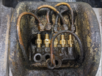
Hello smart, experienced, and helpful folks. Just when it all seemed like I understood what was going on... sounds like so much of life. I ordered new metering units from Monarch but since I had no faith that mine were correct, and the numbers have changed, I now have a mystery as to what goes where. I have searched posts but have not found an explanation for my lathe - a 1957. Below is a photo showing where each line goes and a list of what Monarch sent me. It's like a secret code. I can see why the one larger line would take a different meter but not why there is the variety pack I have.
Also I asked Monarch for the check valve in for the cavity in the top of the apron where the waste cotton sits but received a FRA00 meter unit. Does anyone have the number of the check valve.
Any help would be most appreciated.
Thank you,
Leland Means
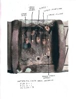
10ee oil quandry.jpeg
 
The FJ prefix means that the input end is threaded 5/16-24.
FJB means the output is set up for 5/32 OD tubing.
FJC means the output is set up for 3/32 OD tubing.

The numeric suffix is the flow rate: 5 is the fastest, 000 is the slowest. Each smaller number passes half the oil of the previous number.

It looks like you have two 5/32 OD lines and three 3/32 lines. You need two FJBs and three FJCs. The cross feed dial needs a lot less oil that the ways, so I would expect to see only one with a slow rate (00 or whatever) and the rest a larger number. The units you were sent make no sense.

FRA-00 has 1/8 NPT input, output for 5/32 tubing, medium slow flow rate.

I don't know the number for the relief valve in the apron, but FRA-00 seems like the wrong part, based on what I know.
 
Last edited:
I just finished doing my 10EE round dial 1942.

This is what I ordered.
The original machine had -00 on all the fittings under the carriage.

After some research here, I upsized the Large Flat and V (for the Z axis way ) to -0; I also bumped the check valve to the 20PSI variant. Everything worked well! The -3 is for the metering unit located in the apron. The LUB G+L is replacement filter for the oil pump.

Hope this helps! I'll be posting a more depth write of my machine later.

EDIT: Listen to Cal on this. My lines were all the same diameter. Yours is not. Don't directly use my chart below for your machine
1714960751639.png
1714962655798.png
 
Last edited:
And yours is a round-dial, so the relief valve in the top of the apron doesn't exist. Instead, there's a T on the side of the apron, next to the thread dial.

Do you have a photo of the B4450 location?
 
Folks reading: This is info is for a round dial 10ee.

Yup! B4450 (20 PSI check valve) is located on the oil pump itself. I also have a poor photo of the T on the side of the apron.
1714999755590.png
1714999813732.png
 
Thank you both for your time and expertise on this. I am glad ratchet mentioned the oil pump check valve as mine seems to be missing.
Cal, thanks for the the numbering explanation. I actually only have one 5/32 line (to the operator side of the ways) all the rest are 3/32. Based on your information I guess I will try this arrangement:
FJB-0 Ways - operator side
FJC-0 Ways - far side
FJC-0 Cross slide (both sides)
FJC-00 Cross slide dial
B4450 check valve (at oil pump)
Leaving one mystery item at the well in the top of the apron.
Thanks again for your help. This entire project would be so far above my pay grade without you.
Now if I can find a used lead screw that is in decent shape I will be nearly there... except for the things I have not noticed yet!
Leland Means
 
Full disclosure, I haven't had occasion to dig into this before and I'm very much figuring this out as we go. Do not treat this a authoritative... Sadly, I don't know if there's anyone left at Monarch that actually understands this stuff and can give good advice.

Check the thread in the top of the apron. It's either 1/8" NPT or 5/16-24.
If 1/8" NPT, I would use a B4450 check valve.
If 5/16-24, use a B3251.
(In both cases these are 20 PSI valves.)
These are my best guesses, see discussion below:

The Bijur literature doesn't really explain how the check valves operate, but I assume that they open at the rated pressure (20 PSI in this case) and will prevent backflow. If that's true, the check valve at the pump should probably be a lower pressure (choices are 5 and 10 PSI) than the one feeding the apron.

The apron check valve functions to bleed off extra pressure and return oil to the apron sump. Without something to bleed off the extra pressure, the pump is sitting there trying to push oil into the system faster than it can seep out of the metering units. With any piston pump, the force on the pump mechanism goes up rapidly with pressure. (Think about an old T-handle bicycle air pump and how hard they get to push as tire pressure rises.) Bleeding off extra pressure should reduce wear on the pump mechanism. (You might want to call Bijur and run all this by one of their techs, see if it makes sense to them.)

Here's a link to the current Bijur catalog: link. Check valves are shown on page 34. Meter units are on page 36.

Thinking about this, round-dials should probably use a B3251 check valve instead of a metering unit in the branch that feeds the apron. (I didn't understand this and put a metering unit in mine.) I read somewhere that the metering units need 15 PSI to operate properly, but the pump can put out way more than that, so the apron check valve can be used to keep the pressure down in the operating range.

If anyone has this all figured out, please chime in.
 
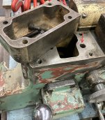
Thanks for the information, link, and speculation Cal. That makes a lot of sense and I will see if I can speak to someone techy at Bijur about the correct amount of pressure at the pump as compared to the top of the apron. While I am figuring oil lines I am trying to understand the logic of the sump shown in the photo. It goes where the ELSR would go. But without the ELSR is it just a bucket to collect oil with no way out? And I assume the channel I marked should be capped. It is threaded. Right now it is open and I am sure connects to the oiling system. Maybe had a Bijur doodad when connected to an ELSR?Seems like a drain on this would be appropriate. Or am I missing something? (first time for that).oil pan.jpg
 
I don't know what the deal is there. But I don't think that area is supposed to be lubricated by the pump. Directly above it is the half-nut assembly and that's open to the back. Maybe someone that's a square-dial expert can help out?

As to the mysterious hole, if you look up inside, it should be plugged. It's the bottom of a drilled oil passage in the apron casting. The passage takes oil from the pump, via a diagonal passage and distributes it to the fitting in the top of the apron and to the O-ring that feeds the saddle oil supply. If you look directly above the hole, you will find the other end of the drilled passage, which is also plugged. If you can run a wire several inches up in that passage without bumping into the plug then that's a problem.

Here's a section of a diagram that shows the oil passages:
monarch_ee-7-22-apron-lube-detail-png.428770


This thread has a discussion about the oil passage:

FYI, years back I spoke to Scott, the lead tech at Monarch, and he told me that they check to see that there is at least 15 PSI at the test port on apron manifold.
 

Attachments

  • MONARCH_EE-7-22 Apron lube detail.png
    MONARCH_EE-7-22 Apron lube detail.png
    22.5 KB · Views: 6
Last edited:
Yep. Thanks the guy. I don't know why mine had its plug removed but it did make it easy to clean goo from the passage. And of course clean the smaller ones shown in the diagram. I still think that I will add a drain plug so oil that falls in has a way to get out rather than removing the unit. 15 psi at the top of the apron. That gives me a great benchmark.
Thanks so much Cal,
LM


Back
Top