What's new
What's new

Engine lathe / screw machine tooling

markwesti

Aluminum
Joined
Apr 26, 2018
Location
Seal Beach , California
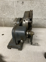
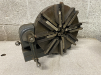
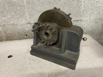
I'm pretty sure this was not made by the "A" word Co. , are we aloud to talk about the "Clau." word Co. ? Avert your eyes if not . Anyhow this is a pretty cool piece of tooling , I think .
Mark .

1709347969694.png
1709349089181.png
 
Last edited:
That's an odd item that I have never seen before.

It LOOKS as if the crank may turn the infeed screw on whichever tool is indexed to it. The ball handle near the crank looks to be on a plunger that either indexes, or both indexes and connects the crank.

Thing is, the tools are all on the same plane, so I don't quite see why you would need (or want) 8 of them.

And there are a lot of adjusters on the backside. They look as if they should adjust the tools, but I am not sure just how.

EDIT: There is also what might be a depth adjuster on each toolholder. That would make sense. It's sticking out the OD end of each toolholder.

This is a case for saving a selection of front and back pics in the thread, just in case anyone has seen one before.
 
Last edited:
They got rare into the ad but missed vintage and antique which generally push up the price.

I'ts amazing some of the stuff they came up with to get finished product off one machine.
 
Looks like a modern turret, but peculiar. Maybe not meant for a standard engine lathe ? Or are the photos flopped ? I could see mounting something like that on the cross slide - if the handle were on the other side, then index and go, index and go. But the stops here are on the other side, kind of like turning towards the tailstock ?

Good idea, actually, better than those dumb four-position things, but set up strange ...
 
Looks like a box tool on steroids, but I think only one cutter is engaged at a time. Each toolholder slides on its own dovetail. The crank has a cam which rides against an adjustable stud to feed in the indexed tool. Maybe there's an internal pawl arrangement where cranking one direction feeds, while reversing increments the turret, similar to a more conventional manual turret action. A short video of the crank action would probably save a thousand words of description.

It would be interesting to see closeups of the tool profiles. Presumably they are set up for a sequence of operations on a single part.
 
@reboots pointed out the tools are on slides with only one at a time in cutting position. A neat little tool, and very handy for a small shop before CNC. I'd be worried about chips fouling the cam followers. It looks like maybe depth stops on the back side.
 
Looks sort of like a Swiss style lathe tool arrangement I once seen...
Interesting, wish I could see it in use!
( But then I'd probably have to have one)
 
This view makes the indexing lock and lock holes in the turret clear.

1709425326085.png

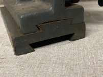
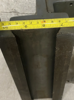
This image makes the riser on the bottom more clear. Looks like the attachment mounts on the carriage in place of the cross slide. And it will fit lathes of two different swings. I will guess that the riser adds .5" to the height, or 1" to the swing. Atlas and South Bend made both 9" and 10" swing lathes and there might be other possibilities. The attachment may have been made by someone other than the maker of the lathes it fits.

The base has to be locked in position on the dovetail to make the turret center line up with the headstock, so there is no need for a cross feed nut. But the carriage can operate normally on the bed, providing for lengthwise turning and maybe one pass screwcutting. The cam follower bearings would suggest that the different diameters that can be turned are limited to reducing the rod diameter as the carriage moves toward the headstock. There would be no chance of a second pass of the carriage once the diameter of the rod was reduced. So you could start with facing and chamfering the end of the bar, and perhaps drill a hole from the tailstock. Then, as an example, you could reduce the diameter for some length, plunge a cutoff tool part way, reduce some more (or less) for some length and then chamfer and fully cut off. Or some combination of diameters and lengths, kind of like a Swiss style lathe, always cutting near the support for the bar, as was mentioned.

1709425369795.png

The riser block fits a cross slide with a 2.75" wide dovetail top. It looks like the turret swivels on the base casting to allow for a small center height adjustment.

1709427437356.png

Larry
 
Last edited:
Yes, and it shows a path burnished in the middle on what looks like a cam that would push the tool carriers, based on the position of one of the two screws in the tool carrier. I initially thought those might be stops.

The position of the screw, combined with a fixed cam, would control depth.

There are two screws in each, so potentially, there are two depths that each tool might feed to. If so, the crank might be movable to engage one or the other.
 
Looks like the cam can slide in and out on the crank shaft.
I'd like to know the purpose of the two concentric rings of "stops" on the back of the turret (not fully populated in the photo). They're not the tool depth stops, which are integrated with the cam followers on the turret OD.
 
  • Like
Reactions: JST
Yes, there is a mark on the shaft that suggests that. Easier than moving the crank.

Agree about the "stop screws". They make me wonder if the disk can move axially, and those stops could maybe be set to cut a wider groove, by using two tools that are used one after the other, at different settings.
 
This is a curious piece , I'm searching for a catalog description . I thought I found it but no , in the 30's-40's there was a Co. called Acorn Machine Tool Co . (English) . They partnered with the "A" word Co. to make a 10" Capstan screw machine . The attachment we are talking about would have been perfect for it .
 
Looks like the cam can slide in and out on the crank shaft.
I'd like to know the purpose of the two concentric rings of "stops" on the back of the turret (not fully populated in the photo). They're not the tool depth stops, which are integrated with the cam followers on the turret OD.
On lengthy reflection I think those are depth stops to "program" an adjacent bar feeder or sliding headstock, positioning the stock for each tool in a Swiss-style setup. Why there are two stops per tool position, I can't say. There's an unpopulated inner ring of 8 holes, maybe for when you don't need the 16-stop functionality.

Perhaps this component is useless without the rest of a specialized machine.

Edit: The mounting dovetail is for quick change. Once you've finally got this thing set up for a job you might rather slide it off, put it on a shelf, and buy another one, than tear it all down again.
 
Last edited:


Back
Top