How to install the app on iOS
Follow along with the video below to see how to install our site as a web app on your home screen.
Note: This feature may not be available in some browsers.
Largest Manufacturing Technology Community on the Web
Stay Connected:
You are using an out of date browser. It may not display this or other websites correctly.
You should upgrade or use an alternative browser.
You should upgrade or use an alternative browser.
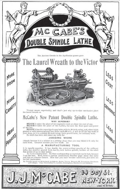
...Photo...McCabe Double Spindle Lathe...
- Thread starter lathefan
- Start date
- Replies 20
- Views 5,619
Tyrone Shoelaces
Diamond
- Joined
- Apr 19, 2006
- Location
- Manchester, England
...click photo for full size...

That'd cause some debate on here regarding headstock and tailstock alignment !
Regards Tyrone.
Joe Michaels
Diamond
- Joined
- Apr 3, 2004
- Location
- Shandaken, NY, USA
The New York City watersheds had a McCabe double spindle lathe in the machine shop at the Ashokan Reservoir. It was the only McCabe double spindle lathe I've ever seen. It was purchased new in about 1915 to do machine work associated with the reservoirs and aqueducts. Jobs like cutting new large-diameter stem nuts for sluice gates and re-facing valve discs were large enough work to need a big-swing lathe. The McCabe lathe at Ashokan was never used during the time I worked there on a NY Power Authority hydroelectric plant. It sat against a wall of the machine shop building. The McCabe lathe at Ashokan had a direct current motor and variable speed controller mounted on the headstock. Originally, Ashokan's buildings were wired for DC, produced by two small "house unit" hydro turbines and a General Electric "gasolene" engine in the lower effluent chamber building. Many years prior to my arrival at Ashokan (1981), the complex was switched onto grid power. The old sluice gate and valve operators remained with DC power and original motors. A motor generator set, and later a rectifier unit had been installed in the effluent chamber. The machine shop was about 1/2 mile from the effluent chamber, and newer machine tools using AC motors were in place including a Rockford openside planer.
During the early 2000's, some desk jockeys discovered that the old McCabe lathe as well as the small hydro turbines with their DC generators and switchgear had asbestos in the form of insulating materials. The order was given to rip all of this equipment out, calling it "asbestos containing material" and hiring an asbestos abatement contractor to remove the equipment in its entirety. The old McCabe lathe wound up in a hazmat dumpster ("skip" as it is referred to in England and Scotland). The old hydro turbines, complete with their Lombard governors (real fine mechanisms with fine machine work) were also treated as hazmat. A buddy tried to get one of the governors or at least a nameplate, but was told everything was strictly controlled and being hazmat, had to be scrapped.
The old McCabe lathe went off to be (probably) triple wrapped and buried in some hazmat landfill. A couple of years later, the NYC Watershed had need of cutting a large stem nut for one of the regulating valves at Ashokan. This stem nut had an inner diameter of something like 10 or 12", and was about 24" long, with a large flange on the body. We got a call up at our powerplant, asking if we could help out our friends on NYC Watersheds at Ashokan. The stem nut was delivered to our powerplant and we took it down into our machine shop. Our crew set it up in the 25" x 96" wide-bed LeBlond lathe and recut the threads. The NYC Watershed machinist came up to our plant, and he told us the desk jockeys and political types down at the main officers in New York City were hell bent on eliminating the entire machine shop at Ashokan. The machinist and crew from Ashokan all knew this was a bad move, but no one could stop it. Before too much longer, the newer machine tools along with the Rockford openside planer all got auctioned off and the building cleared out. There had been a complete maintenance complex at Ashokan which included a sawmill (plenty of trees were harvested on watershed lands) and planing mill. Wood from trees harvested was sawn and milled into lumber for all sorts of projects, outbuildings, or dunnage used in maintenance work. The sawmill was deemed "obsolete" and a "liability" and was cut up for scrap, no effort made to re-sell it to local people who might have used it.
The McCabe lathe was an unwieldly looking machine when I saw it back in 1981-82. It was a nice concept, but, did look like it was a cumbersome machine to setup and use. I believe the same McCabe firm also supplied equipment to railroad and boiler shops in the form of the "McCabe flanger". This was a forming machine which used compressed air to drive a large cylinder. With an assortment of dies, the edges of boiler sheets could be flanged and nicely rounded "knuckles" formed. Straight as well as curved sheets could be flanged on the McCabe flanger, and work could be done hot or cold. I've seen a few McCabe flangers in railroad use on steam locomotive boiler repair and restoration work. It is an ingenious machine and quite versatile. In the hands of a boilermaker with a good head and eye for the work, complex flanged work like boiler sheets with flanged edges and curved contours can be formed. I think the McCabe Flanger, if the firms are one and the same as the McCabe who built the duplex lathe, was built in far greater numbers than the duplex lathe. McCabe lists an address in NY City. I believe this was their offices and headquarters. Having been raised in Brooklyn, NY ( one of the five boroughs of NY City), I always am interested in the machine tool and heavy manufacturing industries that once were in NY City. Years ago, I was told that McCabe actually had their "works" over in New Jersey where the machine tools were built. Or, being a fairly low-volume maker, it is possible that McCabe had another shop building the machine tools to their design. Either way, I do not think the double spindle lathes were ever built in any significant numbers.
Jim Christie
Titanium
- Joined
- Mar 14, 2007
- Location
- L'Orignal, Ontario Canada
There was an other McCabe Lathe in use at a paper mill until recently discussed in this thread .
http://www.practicalmachinist.com/v...mcgabe-lathe-auction-302380/?highlight=McCabe
I don't know where it may have gone after the auction .
I think they may have been sold to several paper mills for doing roll work at a time when paper machine rolls were usually lighter and shorter than they are today .
They could be used on the lower faster spindle for smaller work and the higher one when larger rolls needed work.
Jim
old_dave
Stainless
- Joined
- Apr 15, 2002
- Location
- Central Mother Lode, California
There's is also one of these in the shop at "Rail Town 1897" in Jamestown California.
David
David
Andy FitzGibbon
Diamond
- Joined
- Sep 5, 2005
- Location
- Elkins WV
The Cass Scenic Railroad has a McCabe in their shop. It's actually the third one (if I remember right). The first was lost in the shop fire, and the second was replaced by the current one for reasons unknown to me.
Hendeyman owns one- I'm sure he will chime in. And there's one in a shop in Marietta, OH that a friend of mine works in.
Interesting machines.
Andy
Hendeyman owns one- I'm sure he will chime in. And there's one in a shop in Marietta, OH that a friend of mine works in.
Interesting machines.
Andy
When I lived in Spartanburg, SC back in the late 80's, one of my co-workers had quite a machine shop collection, including a dual spindle very similar to the one Lathefan posted, altho I seem to recollect that he told me it had a 6' swing...?? I'm not certain if it was a McCabe, or another brand.
hendeyman
Stainless
- Joined
- Nov 18, 2005
- Location
- elfrida arizona usa
Joe Michaels:
Another post-1902 model McCabe lathe. It would appear, from everything I have in my files, that the lathes were built in Bridgeport,
Connecticut by a company set up by E.P. Bullard. Considering the close relationship between Mr. Bullard and James J. McCabe and the
fact that the Bullard used machinery business in New York City was turned over to McCabe, it is not surprising that Edward P. Bullard
would have some sort of interest in the development of the Double Spindle Lathe. In several pictures I have of the McCabe Manufacturing plant, the forty foot planer is a prominent feature. About the time that the Double Spindle lathe patents were about
to expire, McCabe introduced the All in One lathe which featured a Headstock mounted on an inclined plane that allowed for adjusting
the swing. I do not have any accurate production figures on the number of Double Spindle lathes that were built, but from information
I have gathered from trade journals and McCabe literature, it was in the hundreds, possibly several thousand. It is interesting to
note the number of Double Spindle lathes that have survived, but I don't recall that any of the All in One lathe are still around.
Over the years, I have posted information regarding the development of the Double Spindle lathe, it should still be in the PM Archive.
Hendeyman
...another ad showing the lower spindle set up for use...
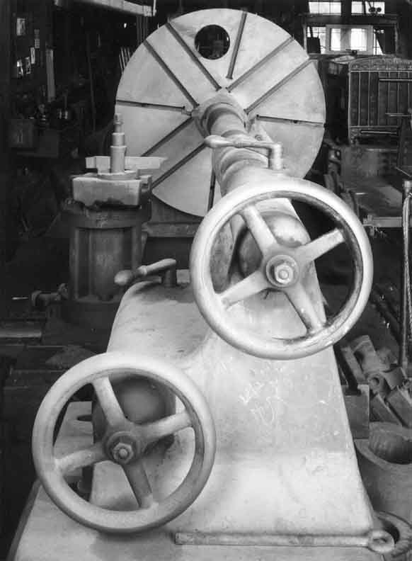
...a couple of photos of the McCabe at Railtown 1897...

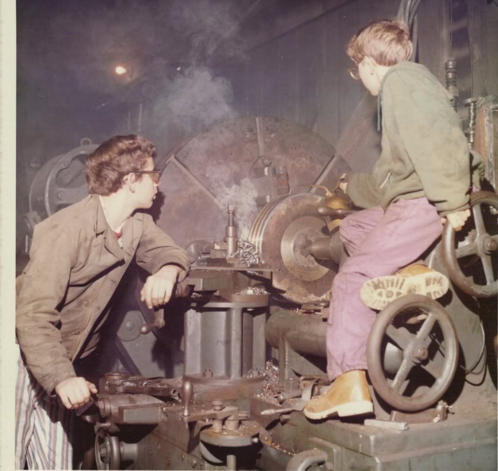
...a really great photo of two young men using a McCabe that appeared on this forum almost eight years ago from member "weber"...he being the young man on the tailstock...this is the future Cass Railroad lathe...at the time in the shop of Paul Weber...
...a couple of photos of the McCabe at Railtown 1897...
...a really great photo of two young men using a McCabe that appeared on this forum almost eight years ago from member "weber"...he being the young man on the tailstock...this is the future Cass Railroad lathe...at the time in the shop of Paul Weber...
old_dave
Stainless
- Joined
- Apr 15, 2002
- Location
- Central Mother Lode, California
...another ad showing the lower spindle set up for use...
...a couple of photos of the McCabe at Railtown 1897...
...a really great photo of two young men using a McCabe that appeared on this forum almost eight years ago from member "weber"...he being the young man on the tailstock...this is the future Cass Railroad lathe...at the time in the shop of Paul Weber...
The black and white of the McCabe is a very fine photograph.
David
northernsinger
Titanium
- Joined
- Aug 19, 2004
- Location
- New England
Recent reporting on McCabe on the vintagemachinery site
J. J. McCabe Lathe & Machinery Corp. - History | VintageMachinery.org
also suggest that McCabe was not the maker and suggests another well known old firm for this role.
J. J. McCabe Lathe & Machinery Corp. - History | VintageMachinery.org
also suggest that McCabe was not the maker and suggests another well known old firm for this role.
jdleach
Stainless
- Joined
- Sep 19, 2009
- Location
- Columbus, IN USA
While I have ran about every manual machine tool made over the course of almost 40 years, with most of my time spent on lathes of all descriptions, a double spindle like this one is something I have never seen in the flesh, much less ran.
If given the opportunity, I would not hesitate to give one a whirl. I figure the set up of one would be a bit of a bear, but would be interesting nonetheless.
If given the opportunity, I would not hesitate to give one a whirl. I figure the set up of one would be a bit of a bear, but would be interesting nonetheless.
Andy FitzGibbon
Diamond
- Joined
- Sep 5, 2005
- Location
- Elkins WV
Recent reporting on McCabe on the vintagemachinery site
J. J. McCabe Lathe & Machinery Corp. - History | VintageMachinery.org
also suggest that McCabe was not the maker and suggests another well known old firm for this role.
At least one of the McCabe lathes I've seen had the actual manufacturer cast into the bed- I believe that it was the American & British Manufacturing Co. mentioned in your link, but I'm going by memory.
The McCabe shown in the photo above- the one that is now at the Cass Railroad- is gear driven by a DC motor with its own genset. I believe this is the third McCabe that has been in use at Cass.
Andy
magneticanomaly
Titanium
- Joined
- Mar 22, 2007
- Location
- On Elk Mountain, West Virginia, USA
I saw a McCabe in a defunct paper mill in Buena Vista, Virginia, a few years ago. Most of the equipment was already gone. I had no way to move it or place to put it at the time. Returning a year or two later, the fellow disposing of the equipment told me that a scrapper had posed as a user to sweet-talk him out of it. One less.
I wondered if the upper spindle would be rigid enough to work effectively.
I wondered if the upper spindle would be rigid enough to work effectively.
hendeyman
Stainless
- Joined
- Nov 18, 2005
- Location
- elfrida arizona usa
lathefan:
Your picture in post#1 is of the improved "Heavy Duty" model introduced in the Spring of 1902. The main improvements were an increase
in swing from 44 inches to 48 inches, moving the "Back Gear" from the back of the lathe to the front of the lathe and an increase in
weight. Shortly after this time, a "Raised Swing" model was introduced that features a swing of 32 inches on the lower spindle and 54 inches on the upper spindle. By 1905. the factory supplied a motor driven model in both AC and DC motors.
The picture labelled as 1897 is a bit misleading as that style of faceplate was not available until a much later date. Referring to
the pre-1902 ad, you will notice that three faceplates were sold with the lathe. A small one, a large plain one and a large geared
one. It would seem that after the 1902 improved model was introduced only the small faceplate and the large geared faceplate came with the lathe, but the large plain faceplate was available on request. The design of the geared faceplates changed a bit over the years,
with respect to the number of slots, both "T" and plain. The large geared faceplate with the hole in it was the result of complaints
from users about the fact that it was a bit awkward to change from the large faceplate to the small faceplate or chuck on the lower
spindle for turning light work. When the large faceplate had to be remove, it was necessary to insert a "tommy bar" into a hole in the
upper spindle and unscrew it while the faceplate was kept from moving by locking the lower spindle. To remedy this problem, a large
hole was cut in the faceplate to allow the driving pinion to be unscrew and removed. then a bushing and an extension spindle could be
installed through the hole and the small faceplate or a chuck could be installed. The large faceplate remained installed and since the
driving pinion had been removed and the drive gears to the upper spindle disengaged, the lower spindle was ready for use. Compared to
removing the large faceplate, this was a very fast and convenient way of setting up the lower spindle for small work, but keeping the
upper spindle ready for the big jobs. The upper spindle is a solid 4-1/2 inch shaft with a large bearing surface.
Originally, the lathes were manufactured by the American Ordnance Company, Bridgeport, Connecticut. At a later date in became the
American and British Manufacturing Company, but I don't have any information on when the change took place. It may have occurred when
Charles Churchill and Company became the British Selling Agents for J.J.McCabe, but that is only a guess.
Hendeyman
lathefan:
Your picture in post#1 is of the improved "Heavy Duty" model introduced in the Spring of 1902. The main improvements were an increase
in swing from 44 inches to 48 inches, moving the "Back Gear" from the back of the lathe to the front of the lathe and an increase in
weight. Shortly after this time, a "Raised Swing" model was introduced that features a swing of 32 inches on the lower spindle and 54 inches on the upper spindle. By 1905. the factory supplied a motor driven model in both AC and DC motors.
The picture labelled as 1897 is a bit misleading as that style of faceplate was not available until a much later date. Referring to
the pre-1902 ad, you will notice that three faceplates were sold with the lathe. A small one, a large plain one and a large geared
one. It would seem that after the 1902 improved model was introduced only the small faceplate and the large geared faceplate came with the lathe, but the large plain faceplate was available on request. The design of the geared faceplates changed a bit over the years,
with respect to the number of slots, both "T" and plain. The large geared faceplate with the hole in it was the result of complaints
from users about the fact that it was a bit awkward to change from the large faceplate to the small faceplate or chuck on the lower
spindle for turning light work. When the large faceplate had to be remove, it was necessary to insert a "tommy bar" into a hole in the
upper spindle and unscrew it while the faceplate was kept from moving by locking the lower spindle. To remedy this problem, a large
hole was cut in the faceplate to allow the driving pinion to be unscrew and removed. then a bushing and an extension spindle could be
installed through the hole and the small faceplate or a chuck could be installed. The large faceplate remained installed and since the
driving pinion had been removed and the drive gears to the upper spindle disengaged, the lower spindle was ready for use. Compared to
removing the large faceplate, this was a very fast and convenient way of setting up the lower spindle for small work, but keeping the
upper spindle ready for the big jobs. The upper spindle is a solid 4-1/2 inch shaft with a large bearing surface.
Originally, the lathes were manufactured by the American Ordnance Company, Bridgeport, Connecticut. At a later date in became the
American and British Manufacturing Company, but I don't have any information on when the change took place. It may have occurred when
Charles Churchill and Company became the British Selling Agents for J.J.McCabe, but that is only a guess.
Hendeyman
..."Railtown 1897" should have been in quotes...it refers to a place and not a date...
CLICK HERE
RC99
Diamond
- Joined
- Mar 26, 2005
That'd cause some debate on here regarding headstock and tailstock alignment !
Regards Tyrone.
I heard they use the Rollie's dad method.

hendeyman
Stainless
- Joined
- Nov 18, 2005
- Location
- elfrida arizona usa
lathefan:
My apologies if omitting the location has caused any problems. My main concern was to call attention to the hole in the large faceplate and because the photograph showed very few details of the lathe, my only interest was to establish a circa and not a location. I used the date on the picture only to state that the faceplate was a much later development. Since my discussion was intended to explain the evolution of the faceplates used on the McCabe Double Spindle Lathes, I did not consider location as being germane. Again, my intent wasn't to offend anyone, but simply convey information.
Hendeyman
Here is a photo of a double spindle on eBay:
Original Photo c 1915 Kansas City NATIONAL MACHINE SHOP | eBay
eBay item no. 260775443625
I have no connection with this item or seller.
Original Photo c 1915 Kansas City NATIONAL MACHINE SHOP | eBay
eBay item no. 260775443625
I have no connection with this item or seller.
Mike C.
Diamond
- Joined
- Nov 25, 2004
- Location
- Birmingham, AL
There is one at an old machine shop in Hattiesbug, MS, too.
Similar threads
- Replies
- 18
- Views
- 510
- Replies
- 8
- Views
- 382
- Replies
- 5
- Views
- 222