holypickle
Banned
- Joined
- Dec 17, 2014
I can't tell if I'm doing this right. My numbers don't seem right, but I don't know enough about programming to know how to test if it is.
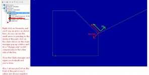
This is just an example part. It's 1x1 inches, with a .5in 45 degree angle.
When I do a finish pass on the OD, the post generates a Z value that isn't at the face of the part.
I'm using a 35 diamond with a .031 nose radius. I'm using "computer" for tool compensation. We don't use wear on our machines, and we don't input the inserts nose radius at the controls, so it seemed like the most logical choice, but it doesn't work.
Please help.
That picture is fail, here's a link to a clearer/larger image
Imgur: The most awesome images on the Internet
This is just an example part. It's 1x1 inches, with a .5in 45 degree angle.
When I do a finish pass on the OD, the post generates a Z value that isn't at the face of the part.
I'm using a 35 diamond with a .031 nose radius. I'm using "computer" for tool compensation. We don't use wear on our machines, and we don't input the inserts nose radius at the controls, so it seemed like the most logical choice, but it doesn't work.
Please help.

That picture is fail, here's a link to a clearer/larger image
Imgur: The most awesome images on the Internet


