What's new
What's new

Mazak multiple offsets 1 tool

Steve007

Plastic
Joined
Dec 21, 2016
Hi thanks for adding me. This is a new problem and we are stumped.
Mazak Quickturn Nexus350myII

Using G-code Mastercam 2017. (Same issue with Mastercam X5)

Something changed we believe in a parameter or setting.In lathe mode used to be able to use 2 offsets for 1 tool. Eg. tool 1 offset 21 or T0121. For when cutting diameters with different tolerances with the same tool. But most recently when drilling with a U-drill then using it to rough bore.

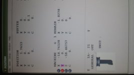
Now it seems the machine is completely disregarding the 21or offset number. It shows up on the screen in the tool details feild as T1 21. but doesn't actually apply the offset from register 21. No matter what, it always uses whats in register 1. This applies for all tools.Im just using tool 1 as an example.

Even if I choose to use one offset only but use offset 21 it still applies the register 1 offset.
Anyone ever run across this before?
Thanks20161221_134657.jpg
 
Here is how I do it...for instance, on station 1, I have four tools...two face towards the main spindle and two face the subspindle. Under tool data, I register four separate tools, with A, B, C, D corresponding to the 1, 2, 3, 4 suffix (Txxxx.Y)

T0101.1 (registered as tool 1A), roughing OD tool for main spindle
T0101.2 (registered aa tool 1B), roughing OD tool for sub spindle
T0101.3 (registered as tool 1C), finishing OD tool for main spindle
T0101.4 (registered as tool 1D) finishing OD tool for sub spindle

...and that works....but there could be alternative approaches.
 
We do not have a Nexus but on our T-plus and Fusion there is a parameter. It is something to do with how to handle EIA offsets. I think it can be set to read the Mazatrol wear. Look through your parameter book and see what you can come up with. I call T0121.02 all the time on all our SQT's. I also do this on our fusion controled Integrex for the sub spindle side.
 
P6 Bit 5 = 1 is for Offset + wear. 0 is without wear

Check P10 Bit 3 and Bit 4
During selection of MAZATROL coordinate systems in the EIA/ISO
program, the wear compensation amount and TOOL EYE compensation
amount in TOOL DATA display are:
P10 (bit 3) = 0: Not added
P10 (bit 3) = 1: Added
Example: G53
T 0 1 0 1
“WEAR COMP.” and
“TL EYE COMP.” are added.
Note:
Refer to “Tool offset functions” of the EIA/ISO Programming Manual for
further details.

P10 (bit 4) = 0
Specify the T command by a number of 4 digits.
T 0 1 0 1
Tool offset number
Tool number
P10 (bit 4) = 1
Specify the T command by a number of 6 digits.
T 0 0 1 0 0 1
Tool offset number
Tool number

(Another handy one ........ )
P9 Bit 6. If it = 0 then G0 rapid is interpolated (straight line)
If = 1 then rapid is at max speed for each axis independently (factory default for most Mazaks)
Per the manual, it doesn't make any difference in rapid time which method is used.
 
Thanks for all the help. It seems all parameters are set to correctly read offset and wear. However it's only reading what's in the tools 1st register. ( T101) completely disregarding any other offset for that tool. We have two identical machines here and it's the same for both. We have an older Mazak slant turn. It will read a different offset.
 
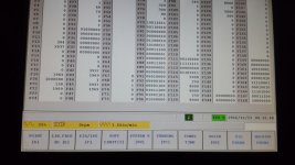
Thanks. You're not the first to suggest a "P" parameter change. Problem is, I can't find any p's. Also, even if I call tool 1 with offset 21 as the only offset. (Without calling offset 1 first.) It still uses offset 1. Page of parameters attached.
Note. We have already looked at the typical paras listed in the book for adding wear to geometry and such. None of those are the issue. Basically,we have 5 pages of offsets that we can use. Offsets 1 thru 96. But for some reason the machine will not use anything other than the corresponding offset to the tool number.eg T0101.
Again. This is a new problem as we used to be able to do this about a month ago. Thanks again.20161223_083244.jpg
 
Not sure. Its only 4 years old.I thought they all came with the same mazak controller. Windows based.


Back
Top