The application is a friction drive.
Simple plate on a shaft pressed to a second driven plate with a friction surface. Much like any automotive mechanical clutch, just not a spring loaded pressure plate "sandwich".
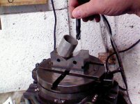
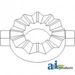
The shaft wise actuator is a three lobe roller ramp, concentric with the mainshaft. A simple radial lever rotates the actuator, the ramps give a shaft wise linear motion to the drive disc, pressing against the driven friction plate and so driving the disc.
Without a dividing head gear trained to a milling machine feed, how would one produce such a "trust bearing cam" suitable for roller between the contacting elements? (hard surfaced and rather precise, say +/- .005 between lobes)
General scope:
5 mm of liner motion with 45 degrees of rotation
carrying shaft diameter about 35 mm.
"agricultural" application,
Bottom line: a friction drive actuator in the least amount of linear space. SIMPLY! There is no room for forks and throw out bearings, plus the direction of actuation is 90 degrees out if the "conventional automotive practice is considered.
If I had a picture of such a mechanism, I would include it.
No need to consider the stationary and rotating parts, that's all covered. 'Just how to make those ramps....?
Ideas?
TIA
ps I can see mounting the work in a dividing head and then "stepping" out a ramp profile, then smoothing the results, harden the working face, followed with some careful work with a slip stone. There must be a better way ;-)
Simple plate on a shaft pressed to a second driven plate with a friction surface. Much like any automotive mechanical clutch, just not a spring loaded pressure plate "sandwich".
The shaft wise actuator is a three lobe roller ramp, concentric with the mainshaft. A simple radial lever rotates the actuator, the ramps give a shaft wise linear motion to the drive disc, pressing against the driven friction plate and so driving the disc.
Without a dividing head gear trained to a milling machine feed, how would one produce such a "trust bearing cam" suitable for roller between the contacting elements? (hard surfaced and rather precise, say +/- .005 between lobes)
General scope:
5 mm of liner motion with 45 degrees of rotation
carrying shaft diameter about 35 mm.
"agricultural" application,
Bottom line: a friction drive actuator in the least amount of linear space. SIMPLY! There is no room for forks and throw out bearings, plus the direction of actuation is 90 degrees out if the "conventional automotive practice is considered.
If I had a picture of such a mechanism, I would include it.
No need to consider the stationary and rotating parts, that's all covered. 'Just how to make those ramps....?
Ideas?
TIA
ps I can see mounting the work in a dividing head and then "stepping" out a ramp profile, then smoothing the results, harden the working face, followed with some careful work with a slip stone. There must be a better way ;-)