What's new
What's new

Small lathe spindle; materials, methods, metrology

Generic Default

Aluminum
Joined
Jan 23, 2016
Location
Wilmington / Long Beach
Hi everyone, first post but I've been creepin' anonymously here for the last 5 years or so.


I'm making a relatively small machine with a sliding headstock and a subspindle. They're nearly identical. I've read as many technical references and forum threads on machine spindles as I can but the spindles are by far the most difficult part of the machine to make correctly. I'll link to some of the sources below.

http://www.practicalmachinist.com/vb/general/lathe-spindle-bearings-design-163580/
http://www.practicalmachinist.com/vb/general-archive/bearings-making-mini-lathe-spindle-80970/
http://www.practicalmachinist.com/vb/general/lathe-spindle-type-grade-steel-167191/
and also;
System rigidity
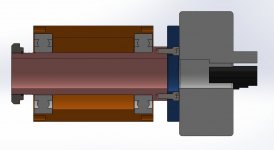
spindle cross 1.jpg
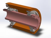
spindle cross 2.jpg
Pink = Inner Spindle Tube
Orange = Outer Bearing Housing
Blue = Face Plate


Anyway, my current design has the machine's main spindles at a 1.25" bore, fitting in 45mm (1.77") angular contact bearings spaced about 4 inches center-to-center. The spindle tube wall thickness is just about 0.25". Overall spindle length is 6.5 inches with a 2.25" face plate flange on the business end and 1.77-18 threads on the other end to preload the bearings with a bearing nut/disc spring washer and hold the drive pulley/gear on the back. The flanged end has 6 1/4-20 tapped holes so the faceplate can be bolted to it later, then a 5 inch chuck or ER40 collet nose will be bolted and centered on that face plate.

That's the inside spindle tube, the part that must spin precisely up to around 4,000 RPM and take all of the turning/milling forces. The OD of the angular contact bearings will be seated in a single aluminum tube (4 inch OD, 3 inch ID) with bored bearing journals. Thermal expansion fit on the 7209 bearings, 85mm OD.

My main concerns are are concentricity and roundness of the bearing surfaces. My plan is to turn the parts in a single chucking operation on a CNC tool room lathe with an 8 station turret. The outer aluminum housing tubes will be chucked, OD turned and faced, then a big boring bar will make the ID bearing journals with a grooving tool. Part off after that.

I don't have access to a cylindrical grinder and I'm not willing to pay $~1,000 to grind and heat treat the inner spindles. I don't need something accurate to a micron, my goal with this machine is to be able to hold overall part tolerances to just under 0.001" during turning operations. With ABEC-3 angular contact bearings, eccentricity is <0.0002". So as long as the spindle tube bearing surfaces are concentric, total spindle runout should be in the range of 0.0005" wobble per 4 inches (or less).


The outer tube housing will be 6061 aluminum. The inner steel tube, I'm not 100% sure about.

I'm leaning toward 4142 pre-hard turned from 2.25 round bar. Other options are 1144 stress-proof from the same size, or starting with 2.25 A513 DOM steel tubing to avoid drilling through with a big drill.

4142 = 90,000 PSI yield
1144 = 100,000 PSI yield
A513 = 70,000 PSI yield

The spindle is fairly short and will not be used for hogging inconel or anything with huge loads, but I don't want it to bend or break over time from fatigue, especially around the flange neck area.


Does anyone have advice for me? I know some of you are experts on spindles. Is my plan decent or will it be a complete fail?
Thanks!
 
Just wondering, what volume do you think you will have, and is this something you do full time or a hobby. The reason I say this is that quite likely if you are going to make any quantity of these the bearing companies likely have an applications engineer who will give tons of great free advice. One other thing is check on the bearing manufacturer's websites they all have a bunch of excellent engineering info to help with selection of bearings. I have this old ********* book that is great and covers machine tool spindle design in it. I suspect it will get you close to where you want to go.

BTW ABEC 3, sounds awfully low for a machine tool spindle I would think you would want 7 or 9 if for nothing else than that is what a customer would tend to expect on a proper machine tool.
 
These first two are just prototypes, if I move to production I'll go for a stronger/harder spindle material and do small batch runs at a grind shop. Same reason I'm using ABEC-3 instead of the normal ABEC-7, trying to keep costs down on this first unit. No reason to put in $1,000 bearings when the inner spindle is only accurate to a few tenths.

Also, this is definitely not a proper machine tool, at least not yet! Mostly going to do plastic and aluminum, no aerospace or medical type parts so I don't have to hold ridiculous tolerances all day. Right now I'm really just going for a semi low cost spindle and headstock assembly.
 
One should never mix materials, certainly not aluminum and steel on the same spindle assembly as thermal expansion is very different. Both should be steel. Otherwise you design and machining scheme are OK for low duty, medium precision operation.
Rather than boring two concentric bores for the bearings in the housing, it is easier (and more common) to make one through bore the size of the bearings OD and to secure a spacer inside the housing. An alternative is to use flanged bearings that eliminate both the two separate bores and the spacer.
 
Just a thought - how do you want to remove front bearing without destroying it? What tolerances do you plan for bearing jurnals? (If both spindle jurnals are in j5 tolerance assembly will be a pain. Disassembly almost impossible).
 
Absolutely !
A big no on alu and steel - wont work at all.

A lathes spindnle should heat 20-25C delta T.
This will crap out your preload (3C = 2 microns at 50 mm => 16 microns difference).

Also, use the spacer or two threads to tighten spindle in place.

One should never mix materials, certainly not aluminum and steel on the same spindle assembly as thermal expansion is very different. Both should be steel. Otherwise you design and machining scheme are OK for low duty, medium precision operation.
Rather than boring two concentric bores for the bearings in the housing, it is easier (and more common) to make one through bore the size of the bearings OD and to secure a spacer inside the housing. An alternative is to use flanged bearings that eliminate both the two separate bores and the spacer.
 
Further advice.
Sink the planned faceplate, so its on the face, and reduce overhang by 40% or so.
Triple the rigidity right there.

Overhang cubed = rigidity.
 
Thanks for the quick feedback everyone!

I'll make the face plate thicker with a big countersunk hole in the middle so it fits around the inner spindle flange. Should improve rigidity a bit.

I'm not sure if I have the capability to bore a 6 inch 85mm journal to the tolerances I need. I figured it would be best for rigidity and strength to make the aluminum tube a solid piece with the bearing journals and register faces done in one operation. As far as thermal expansion goes....

The bearing centers are about 4 inches apart. If the spindle spins fast, everything heats up. I'm assuming that roughly half of the heat generated in the angular contact bearings will be absorbed by the inner steel tube, and the other half will go into the aluminum outer tube. The steel tube will absorb heat slower and release it slower as well; the aluminum tube will suck up the heat and immediately dissipate it by convection/conduction with the surrounding environment. My electronic control system is a bit unusual for CNC in that I can pre-heat and turn on fans to cool components where I need to.

My basic thermal design involves both the inner and outer tubes heating up during operation. The aluminum expands about twice as much as the steel for a given temperature increase. When the aluminum expands, preload increases since the bearings are preloaded with the inner races. When the steel tube expands, preload decreases. This means that thermal expansion in the assembly should (in theory) oppose changes in the overall spindle preload, rather than cause a thermal runaway like if the outer races were preloaded. There will still be a small change in preload at high speeds but I can't accurately predict it yet. I'll do some FEA for the next post(s).


As far as tolerances go, the outer aluminum tube shouldn't need really tight tolerances. I'll try to keep the journals about 0.002" undersized so that the thing can be fitted together by heating the aluminum tube before installing the bearings. The 0.002" should keep everything tight when it starts to heat up. As long as it doesn't get hotter than the temperature it was installed at, the bearings will stay in place and concentric.

The inner steel tube will be hard though. I won't be able to separate the inner bearing races from the inner spindle tube once installed. I believe I need to get the steel tube bearing fits to be just a tiny bit oversize, no more than a few tenths, so I can do a freezer-fit. I don't have bearing pullers to take them off if I need to, so I think the assembly will be permanent.


What about the material for the steel spindle tube? Will 4142 pre-hard work for this? I can't really think of anything better that doesn't require heat treat or grinding. I've even considered 17-4 in the H900 condition so I can get 170,000 psi yield and RC 44 hardness, plus the whole thing about it not rusting!


Btw, I don't want to come off as condescending or dismissive with my posts in this thread; I kind of argue when discussing design stuff like this, but I take you advice seriously and use it for design iteration. Just know that I juggle around your advice and ideas with my own thoughts to try to make a better end product.
 
I dont mind the back-forth, but its a Really Bad Idea to put alu anywhere near the spindle.

FEA wont help.
Fwiw.. Alu expands 3x as much as steel.
Its also light, when you want heavy.
 
Spindle cartridges are readily available. For not much over 4x the cost of abec 7 bearings too.
 
Spindle cartridges are readily available. For not much over 4x the cost of abec 7 bearings too.

Yep! Or buy a whole Taig micro-lathe for a couple of hundred bucks, throw the rest of it in the bin, and re-machine the ... wait for it ... aluminium casting micro-lathes are typically made of, then go down to the pub for the rest of the day. Given you'll be done by 10, don't plan to drive home after that arduous "job". :ack2:

Those things are good for 7,000 rpm and the runout is within what the OP wants.

Next ...!
 
I think you missed the part about the 1.25" spindle bore ...

Yep! Or buy a whole Taig micro-lathe for a couple of hundred bucks, throw the rest of it in the bin, and re-machine the ... wait for it ... aluminium casting micro-lathes are typically made of, then go down to the pub for the rest of the day. Given you'll be done by 10, don't plan to drive home after that arduous "job". :ack2:

Those things are good for 7,000 rpm and the runout is within what the OP wants.

Next ...!
 
Well I obviously wasn't being entirely serious about using a Taig product per se! The point is those small lathes use aluminium headstocks and the world doesn't stop turning as a result of steel touching aluminium!!!
 
Its completely different.
An all alu machine is just that. No differential expansion.
Low rigidity.
Low workload.
Not "serious" as in 1.3" spindle bore and real bearings.

An all-alu machine can function, imho ...
Sherlines work fine.
But the bearings are so small, expansion is hardly a concern.
And they are 1/10 the power contemplated.
but alu/steel is unlikely to be "good", especially in over 1.3" spindle bores.. or 45 mm D bearings. No way.

The OP asked for advice.
He got it.
Weather he takes it .. totally up to him.

Well I obviously wasn't being entirely serious! The point is those small lathes use aluminium headstocks and the world doesn't stop turning as a result of steel touching aluminium!!!
 
Aluminum is used as a housing material in a lot of high end router spindles, so it certainly can be done. Omlat 24 K rpm spindles are all that way. Steel shaft, aluminum front housing. The bores are tighter than normal size wise and they use a cooling liquid to maintain temperature. However in your case I agree that steel would be better. I would ditch the shoulders in your housing unless you can grind them with an ID grinder and use two precision ground spacers. There is no real reason to invent your own setup. Copy someone who put in the time to do it right.

A very simple lathe spindle is what Hardinge used for years. Two angular contact bearings, two precision spacers used to set the preload. Note you need the right contact angle of bearings because lathes take a lot of radial load. Outside spacer is captured in the housing. You do NOT want interference fits in machine tool spindles. Typical specs in this size range would be the shaft 0 to 3 tenths under the bearing size and the housing 0 to 3 tenths over.

The two spacers much be ground flat and parallel (As in less than .0001) Default is the exact same size but you can adjust preload by making one spacer a tenth or two longer or shorter.

Search for Hardinge spindle drawing and you might find a drawing out there.

Also, If you are chucking your housing while turning it it is going to probably be distorted when you remove it.

Making spindles is not some black art but you do need to have the right knowledge and some tools. If this project means much to you beyond a hobby I suggest having someone help you with it. There is a reason I have worked on hundreds and spindles of all different types and none of them have been made as crudely as you are speaking of.

If you need any help send me a PM. I worked as a spindle re-builder for a number of years and now run a shop does a fair bit of machining and precision grinding on spindle parts. It may not be as expensive as you thing to farm out a small portion of it.
 
Aight, I did more calculations and thought about the assembly method a bit. Here is the plan, or three plans really;

1) Build the aluminum housing, steel spindle setup as you guys recommended against.
2) If that doesn't work, or it if fails, I'll remake it with a steel housing.
3) If that fails too, I'll look into getting a job shop to make it, one that has a cylindrical grinder.


All my analysis with the thermal design seems to contradict what you guys are saying, and I think it's worth a try given that a failure will be a loss of no more than ~$200. i might make something great. If not, I'll redesign to make it like you describe. If there were any normal big-bore through spindles on the market for a reasonable price, I would be all over it. Seems like 99% are cartridge spindles for cheap mills though.


One more question!. To preload a normal lathe spindle, you would put a disc spring/belleville washer between the bearing race and a bearing nut, then tighten until the preload is correct? Or do you just put the bearing nut directly up against the bearing race? I've heard some contradictory stuff that made me unsure about it. Seems like having a disc spring would prevent tiny changes in spindle length from thermal expansion from ruining the bearings. My bearings are 40 degree contact so they can take a ~4000lb load axially.
 
The inner steel tube will be hard though. I won't be able to separate the inner bearing races from the inner spindle tube once installed. I believe I need to get the steel tube bearing fits to be just a tiny bit oversize, no more than a few tenths, so I can do a freezer-fit. I don't have bearing pullers to take them off if I need to, so I think the assembly will be permanent.

You won't be able to reduce preload in that configuration (at least not without abusing bearings) - could be a little bit of problem in a test unit.
 
One more question!. To preload a normal lathe spindle, you would put a disc spring/belleville washer between the bearing race and a bearing nut, then tighten until the preload is correct? Or do you just put the bearing nut directly up against the bearing race? I've heard some contradictory stuff that made me unsure about it. Seems like having a disc spring would prevent tiny changes in spindle length from thermal expansion from ruining the bearings. My bearings are 40 degree contact so they can take a ~4000lb load axially.


Preload on normal lathe spindles are done with precision spacers. Springs are not common. Lots of times rear bearings will "float" in the housing. They are constrained on the shaft but not in the housing. This allows thermal growth. Most real lathe spindles will have a roller bearing in the back. Sometimes a straight one, sometimes tapered.

Typical setup is tapered roller bearing in the front, followed by a pair of angular contact thrust bearings. This is all locked up in the housing in the front. Rear bearing is the radial one and its job it take the radial loading of the gears or belts.


Springs are more common in precision grinding spindles and high speed spindles. Your bearings are small with low rpm you should not be generating much heat at all.
 
Last edited:
You won't be able to reduce preload in that configuration (at least not without abusing bearings) - could be a little bit of problem in a test unit.


Oh, I see now. The rear bearing must be able to slide axially along the inner spindle tube in order to change preload. Derp.

I guess I'll have to machine these spindle tube bearing journals to really close tolerances. Probably gonna have to do a bunch of finishing passes, then sand them with fine grit paper and check with a micrometer. If I go undersized by taking too much off, the bearings will slide freely but the spindle will have more axial runout. I suppose a few microns extra of axial runout is still within my tolerance expectations since the bearings are 4 inches apart.

I might impinge the spindle journals with tungsten disulfide to reduce this problem; it will add 1 micron to the OD of the tube, or ID of the bearing, and will keep the friction down to 0.04 (1/10th of steel on steel). This may help when adjusting the preload with the bearing nut. I can make a light interference fit by heating the bearings while freezing the spindle tube and assembling while there is a temperature difference. Taking it apart is the difficult part since the bearings and the inner spindle have the same thermal expansion. The WS2 would help with disassembly, and assembly, and would give me a bit of a tolerance buffer. Hope I'm not coming off as crazy, I'm just limited by my tools. All I want is a mediocre spindle for a prototype.
 
The OP asked for advice.
He got it.
Weather he takes it .. totally up to him.

A big no on alu and steel - wont work at all.

Yes. Crap advice as it turned out!

Just to refresh your memory, here's the requirement.

The spindle is fairly short and will not be used for hogging inconel or anything with huge loads, but I don't want it to bend or break over time from fatigue, especially around the flange neck area.

The spindle will turn at 4,000 rpm, and requires finished part accuracy of a whopping 0.001" and runout 0.0005" at 100 mm. So unless you see some decimal places in different places to what I do I'd hardly call that a "serious spindle" by any stretch of the imagination! It sounds as if he has done his homework well and is on the right track. I've seen many examples of aluminium housing spindles, indeed as far as I'm aware all the new high speed cartridges sold for DIY routers etc are all aluminium housing, and they're good for 20K rpm!!! So obviously it can be done, with the appropriate considerations.

To the OP, sorry I'm no spindle expert, but if it was me I'd be using 4140/4142. But only because there's just that and 1020 in my world ;)


Back
Top