What's new
What's new

weird question, need to direct magnet energy

Kevin Quitberg

Plastic
Joined
Oct 3, 2011
Location
Wyoming
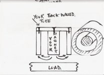
I am trying to make some kind of enclosure for a neodymium magnet to orient the pulling force to one end of the magnet. I have made a sleeve of ductile iron to enclose the magnet circumferentially as well as on one end, leaving the end I want most of the magnetism on open. The magnet is supposed to lift in excess of 100 lbs. but I don't seem to be getting anywhere near that strength. It is an N52 rated magnet, .922" O.D. x 1" long.

So, some questions: Is a small hole in the magnet able to orient the pulling strength to the ends? Is there a better material to enclose the magnet with? Is there a minimum thickness of the jacketing material around the magnet? I have contacted some "magnet companies" but all their "engineers" live...guess where.

I am trying Practical Machinist on an off-topic question but it seems there is always an answer here for everything. Thanks in advance, KQ
 
This is from Applied Magnets. They have always been real good with delivery, prices, etc., and I have taken them for their word on strength. I am not getting anywhere close to 75 lbs. either. Closer to 30. Thanks, KQ
 
Lifting steel, 4140 usually, sometimes a little 17-4PH. Need to be able to lift about 50 lbs out of a 4' deep 2.1" inside dia. pipe. Have to be able to release it when installing a new piece so I have a rod through the magnet to push the magnet away or a sleeve around the magnet so I can push a hollow piece away from the magnet on the end of the rod. The magnet is on a piece of aluminum tubing 4' long.
 
What material if the pipe? If it is iron or steel it could be "stealing" some of the field. If it conductive but not even magnetic (aluminum or copper) and you try and lift the load too quickly you will get some weird Lenz's Law effects. Even if you move very slowly it will affect your magnetic field.

-DU-
 
The pipe is carbon steel. The problem is that people are trying to use the tool outside the design parameters. Originally I didn't have to lift more than 12 lbs. Now that it is possible to do that, other possibilities have arisen. You all know the story by now. However, if I can make the thing lift 50 or 60 lbs., which should be possible, there are many more sales in the offing. That is a good thing. Eventually the theoretical will be exhausted. I just can't seem to get the lift promised with the magnet's rated capacity and wonder what I am doing wrong. There has to be some design clue in the material surrounding the magnet that I am missing or don't understand. KQ
 
Assuming it is a 'pot' magnet with Nth at one end of the cylinder & Sth at the other, do you have a brass or aluminium sleeve between the magnet & the iron enclosing pipe? And do you have an iron disc 'bridge' over the non-contact end? Both these things you need to have. A plastic sleeve would do instead of brass for the pedantic but brass or aluminium are more workmanlike.
 
Oh yeah, you do need a nonmagnetic sleeve over the sides of the whole thing to avoid 'shorting' flux into the pipe you're trying to retrieve that slug from.
 
Width of "magnetic insulation sleve" is crucial. It determines how far out the magnetic flux jumps the gap, that intern decides how thick the optimum part is to get maximum grip. Sometimes on thin pieces you can get far better actual lift from multiple smaller magnets. Have a look at permanent magnet chucks for surface grinders, should give you some good ideas.

Don't forget alloys have varying magnetic properties, both with composition, temperature and heat treat.
 
Like I think Swarfless was describing, you have to horseshoe the magnet to bring the opposite pole to the same end. A nonmagnetic sleeve to enclose the diameter, but not past the end. Then a magnetic sleeve, enclosed on the end, that the opposite end will touch. I don't know, but suspect flatness of this surface is important. This will get both poles to the same end, one inside the other. If the assemble is to be pressed into a magnetic steel it needs another nonmagnetic sleeve first.

Surface finish of the attracted metal is very important. I think tests are done on a ground surface of a very magnetically susceptible steel. Just a few thousands can lessen the magnetic attraction significantly, whether the gap is from grunge, mill scale, surface roughness, or some other spacer material.
 
Seems like a larger magnet should work, too. Or, an electromagnet, whose field strength can be easily varied to suit. The part could then be released without any moving parts in your gizmo. With force over 100lbs, it won't be nearly as easy to release mechanically as it is now.

Dollars to donuts, there's someone out there already making an electromagnet that might work.

How close is the contact between the part and the magnet? That can make a big difference in holding power, too.

Neil
 
Assuming your magnet has the poles already on the faces(both ends) You need a piece of steel on the opposing side(1/4-1/2"), this will strengthen the pull force on the open face. I'm not sure how much on a 1" long round magnet, more used to 1x1x.5.
 
magnetic "flux" passes through materials based on their properties. Air is a poor medium, steel is relatively good, in general.

So.... a practical description, without pretending to be rigorous and perfectly correct.....

1) flatness is important. A bumpy surface allows nearly direct passage of flux in the contact areas ("contact" area still has an air gap), but the flux must pass through air elsewhere. magnetic "force" is "used up" by passing through material, so if there is an air gap, much of the magnet's strength is used up forcing the field through the gap, and that much less is available for lifting (less flux gets into the lifted material).

2) a "pot" magnet structure will indeed lose some strength due to flux "jumping the gap" between the side iof the magnet and the surrounding "pot". But this tends to be at the ends where the field is strongest.

3) flux follows the best path, if the path through iron is easier, less will jump the gap. make sure there is enough thickness of material at the end of the magnet (bottom of the "pot"), or the iron may saturate. Then the rest of the flux (the amount OVER the saturation flux) cannot "see" the iron, and behaves as if there was no iron. Only the saturation-limited flux is "in" the iron, limited by the area where the field is strongest and cross-section smallest. That's normally the bottom of the pot, where ALL the flux has to "fit in" the iron.

4) for lifting, flat surfaces in the magnet are great, but a bumpy or non-flat surface on the ;lifted material works the same way.... it limits the flux and the lifting force. So lifting tubing can be problematic, especially from the side. A fitted "shoe" that conforms to the surface can do a better job sometimes if the same material is always lifted.
 
I took an old hard drive apart awhile back, just out of curiosity, and there were two magnetic "plates", roughly 1" X 2" , kidney-bean shaped; that faced each other, between which the arm that reads the disc pivoted.

After amusing myself by spinning the shinny disc around for awhile, I decided the magnets would prove useful so I removed them, and they are very powerful, bonded in some way to a metal mounting plate, maybe 1/8" thick. What's odd to me, is that there is no magnetic attraction on the off side of these magnet/plate assembly. If you stick the two plates together magnet-to-magnet, it's difficult to separate them. Place them back-to-back, they wont even stick.

Place one on the toolbox to hold a drawing, it has to be pried off. Turn it 180 it wont even hold it's own weight.

What wizardry is this?
 
Hi Kevin

There is no such thing as a magnetic insulator. Anything non ferous in the gap between the core and the outer tube is no more effective than air .
There is a metal known as Mu metal that is used in a computer Hard disc enclosure for instance to protect the disc data from the powerful magnet that produces the field for the coil to move the heads between tracks . It works by 'Trapping' all the flux due to its very high magnetic permiability. The magnetic field produced by two very powerful permanent magnets is 99.999% contained within the metal magnetic circuit with virtually no stray field outside of that magnetic circuit. The only part of field circuit not metal is the air gap in which the moving coil resides. The Mu metal circuit, as well as protecting the disc data also means that the field intensity is concentrated where it is most needed for the coil to react.
I presume that what you have constructed is as I have attempted to draw. The outer tube is providing a high permeable path from the rear of the magnet to the load so that ALL the magnetic flux is using the ferrous load to complete the magnetic path/field . It is important that the surfaces of the magnet core and the outer tube are exactly flat with respect to each other to ensure a metalic seal with no gap. Any air gap allowed to occur in
the sealing action will reduce the lifting power acheived . There would be a reduced load lifting force even if the metal to metal seal is only prevented by a coat of paint on the load. Incidentally, if you manage to get a powerful lifting action. you are not going to be able to poke the load item off the magnet.
As suggested earlier by Bill and Neil, Electromagnet is the way to go as they do in scrap yards .

Davycrocket

The Mu metal in the hard disc magnetic circuit is the cause of the 'Wizardry' mentioned in the post above .
 

Attachments

  • Magnet (Small).jpg
    Magnet (Small).jpg
    32.8 KB · Views: 731
Last edited:
The ID of the pot must be as large as possible to reduce magnetic flux through the gap instead of through the part and the pot must have enough material to carry the flux. Too little saturates and limits the flux. You would be better to turn the magnet on its side with pole pieces on both ends, turning it into a horseshoe magnet or better yet, get a magnet made that way. The material also limits the pull since its permeability and saturation characteristics limit the amount of attraction regardless of the amount of magnetism applied.

Davey, Jerry et al are correct that there is no magnetic insulator.

Bill
 
A good source of mu-metal for experimenting is old oscilloscopes. Look for a shield that completely surrounds the CRT, and watch out for charged capacitors, of course.

Chip


Back
Top