Paula
Titanium
- Joined
- Sep 16, 2005
- Location
- Indiana, USA
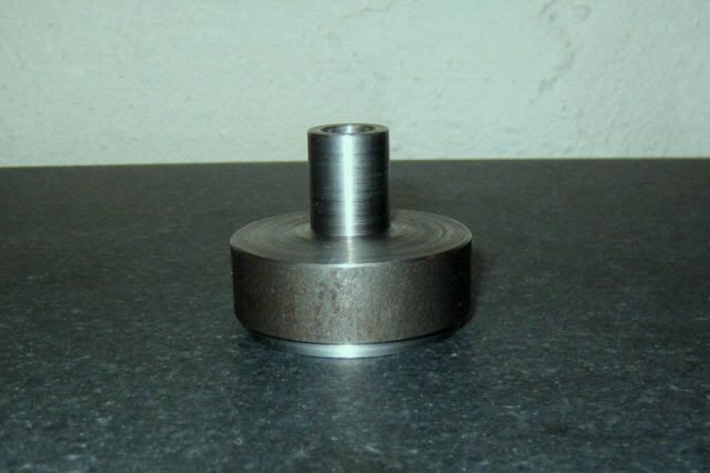
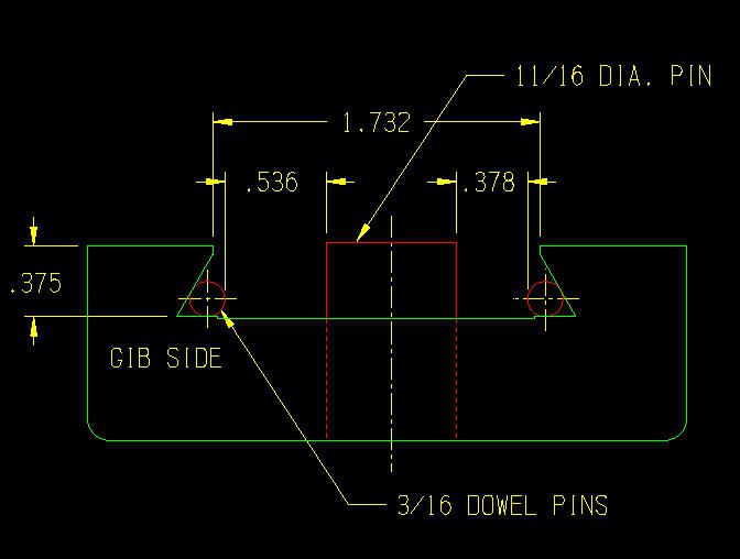
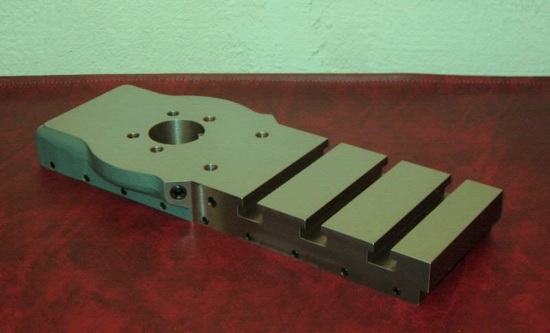
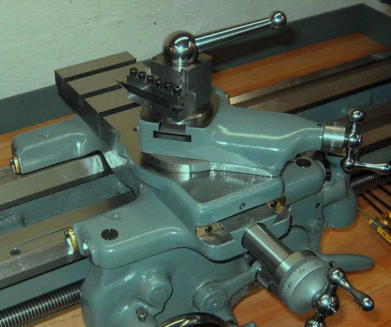
Here’s another Metal Lathe Accessories project: the S-4382 T-Slotted Cross Slide. I’ve wanted to equip my 9A with one of these since I bought the lathe in ’05, but have only recently got around to it. The t-slotted cross slide, in addition to providing the normal functionality of the stock SB cross slide, extends the working surface completely to the rear end of the slide, providing t-slots and additional tapped holes for securing workpieces. When completed and installed, the S-4382 slide offers some important advantages over the stock South Bend cross slide:
1) The t-slotted cross slide, with its substantial horizontal working surface, makes possible certain boring mill-type operations on the lathe. Accordingly, it facilitates between-centers, or "line boring" operations.
2) It provides for the use of a rear-mounted toolpost.
3) It enhances the usability of a milling attachment, in that the attachment can be mounted at several locations along the cross slide, in addition to the usual compound rest position. If you already own a mill, even a quite large one, there is still no denying the handiness of the milling attachment for machining the ends of long workpieces, as the z-axis clearance of any lathe is essentially unlimited. (Metal Lathe Accessories also offers an auxiliary milling attachment base kit for mounting the attachment at locations other than the compound rest mounting hole.)
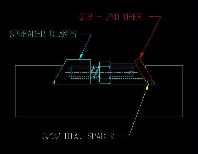
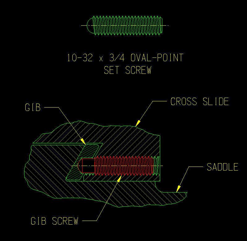
4) The S-4382’s dovetail ways extend the full length of the slide, and, provided you machine a new gib of corresponding length, provide an arguably more substantial, and longer-wearing guiding arrangement for the cross slide. Also, due to its larger dimensions (both length and width), this slide offers better protection from swarf contamination of the sliding surfaces. The stock “duckbill” extension of the SB slide is particularly onerous in this regard, as bits of swarf migrate underneath the duckbill. Inaccessible, they remain to become trapped between saddle and cross slide, unless the entire cross slide is removed to clear them out.
5) The semi-circular “wings” which surround the mounting hole for the compound slide are slightly larger on the S-4382, providing ample room for radial index marks at the four polar locations. Having index marks at these additional locations greatly simplifies setting up the compound at various odd angles.
6) The t-slotted surface provides a handy place to set your can of cutting fluid whilst machining operations are underway. (Well, it does.)
7) It’s a fun machining exercise, and the finished slide looks cool.
As with all of the Metal Lathe Accessories kits I have thus far machined, the S-4382 kit proved to be of excellent quality. The machining instructions and drawing are clear and concise, and the casting machines beautifully. Also, while the S-4382 cross slide is intended for the 9”/10k lathes, at least one other forum member has machined an S-4382 for a 10L.
Many of the MLA accessory kits, with a bit of ingenuity, can be machined completely on the lathe itself -- no mill required. Unfortunately, the S-4382 is not one of them. You don’t need a large mill -- the cross slide project fit handily within the work envelope of my SX3 bench mill -- but you need to at least have access to one. If you don’t, you may want to consider having one machined for you. Earl Bower, of Bower Machine, offers the service at a reasonable cost, though I do not endorse his packing methods (see this post).
As always, keep in mind that there are many methods to accomplish the same result, and this account is just one builder’s approach. I welcome any comments on the methods used here, and am more than glad to hear about how others have done it (or would do it.) Also, this report will be presented in multiple, discrete posts as time permits, but feel free to add your own comments in the meanwhile.
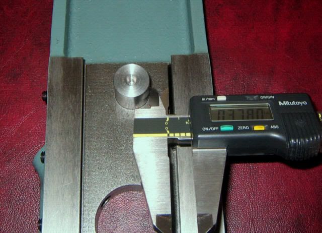
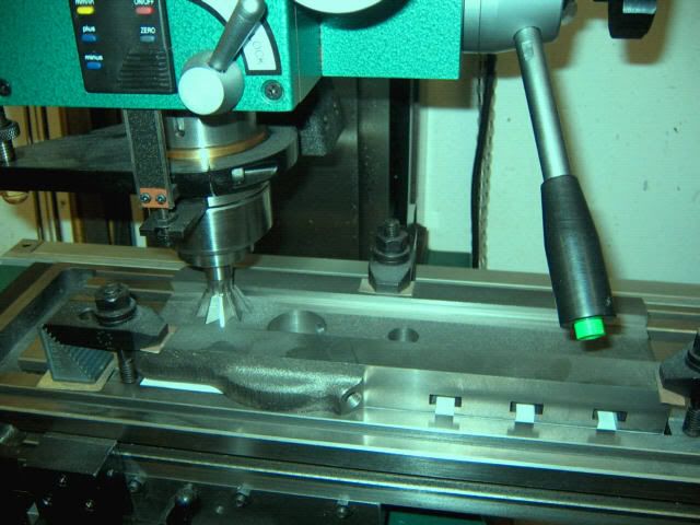
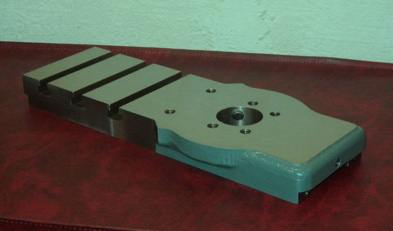
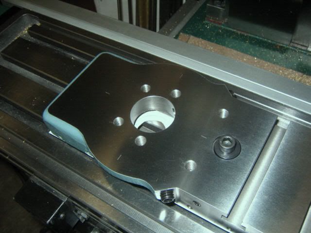
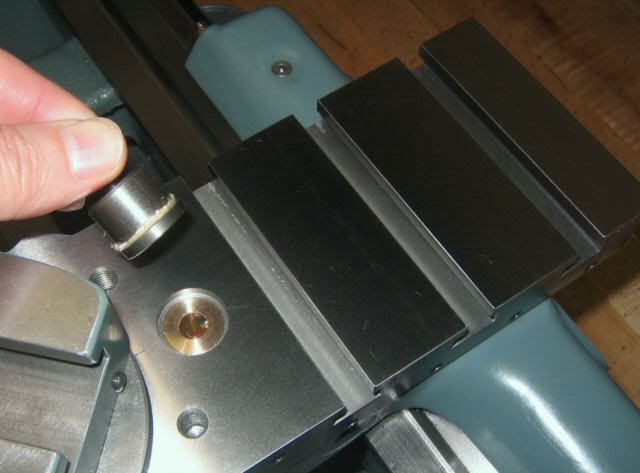
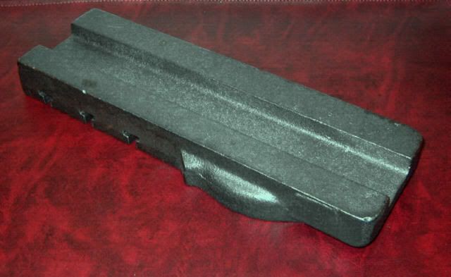
Here are some pics of the raw casting. The first is from the top side, after I cleaned off some of the high points with a file. Note that the t-slots are cored to rough undersize dimension, to facilitate their machining:
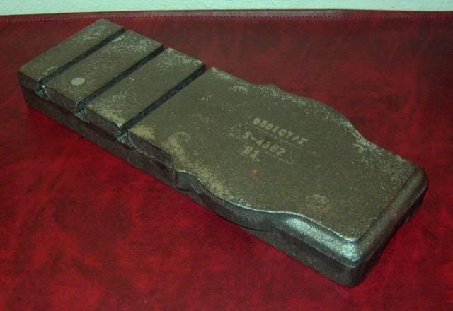
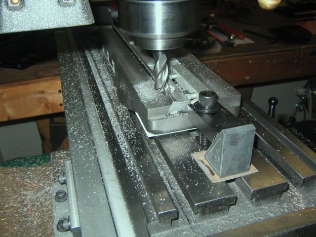
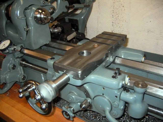
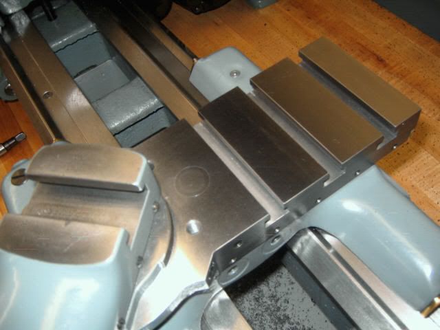
And here’s the bottom side, showing where the dovetails will be machined:
Machining Top & Bottom Surfaces
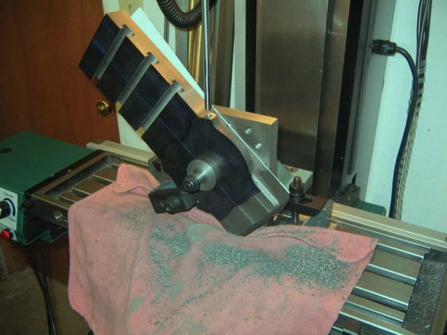
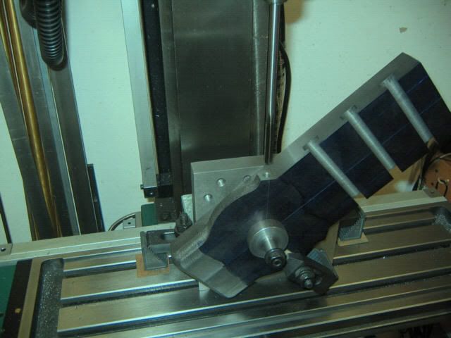
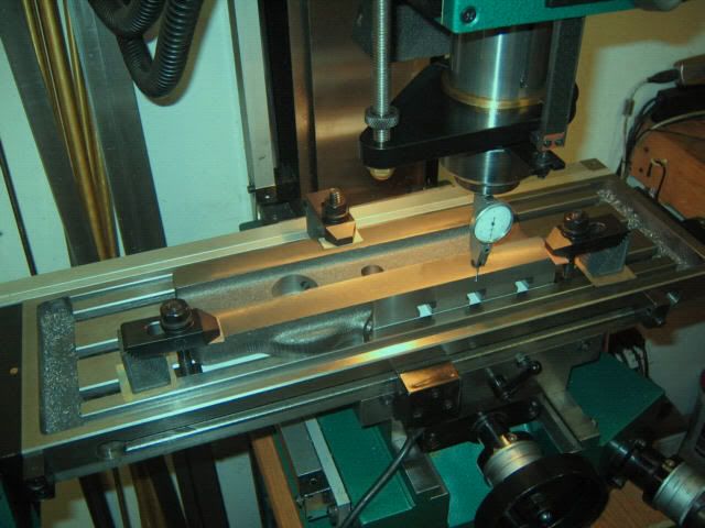
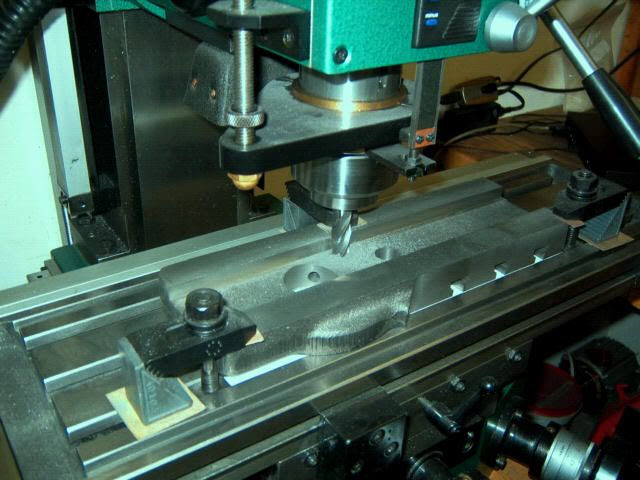
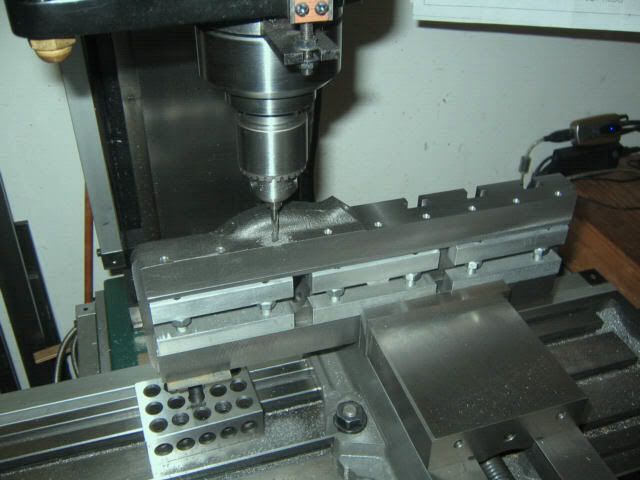
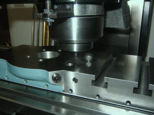
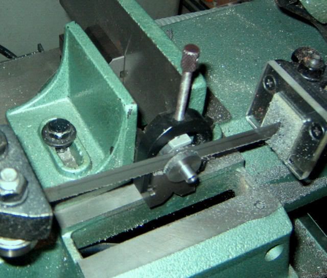
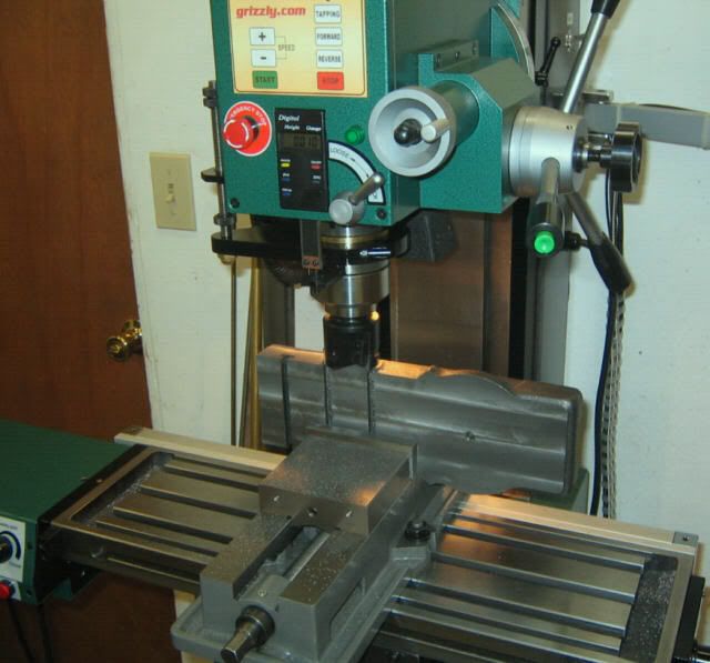
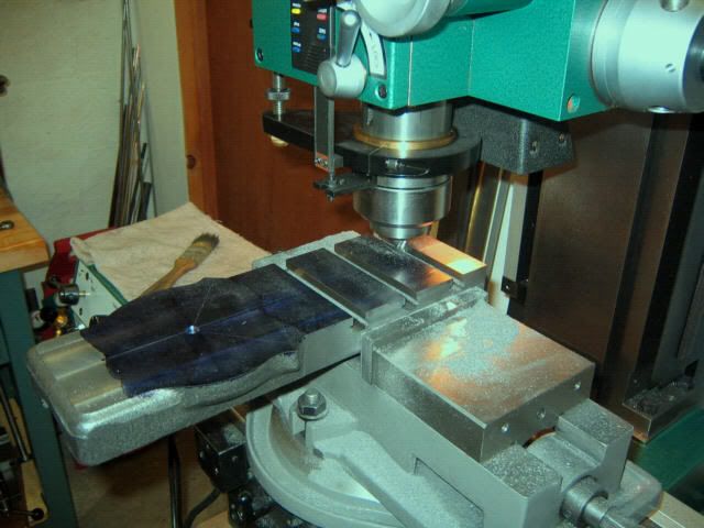
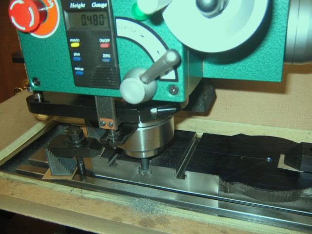
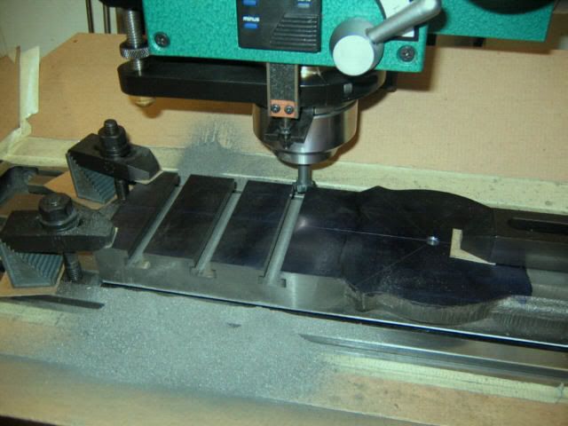
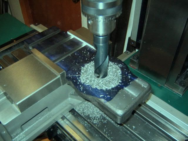
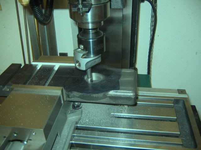
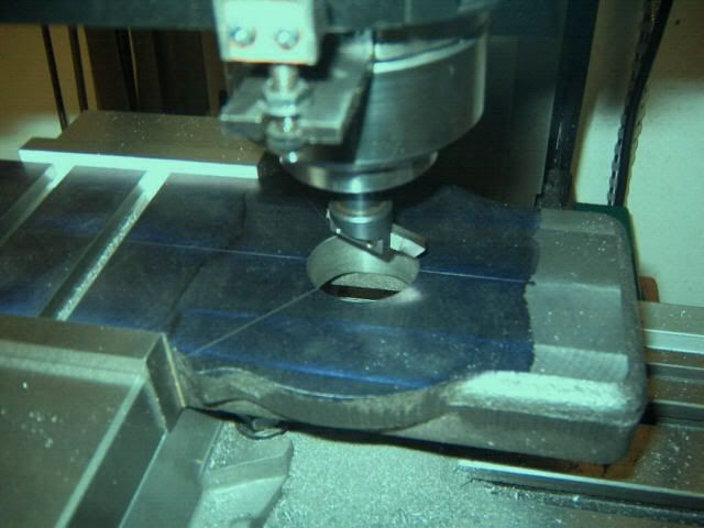
For machining the top and bottom surfaces of the casting to rough dimension, I clamped the casting to the mill table, after placing a thin piece of card stock material between table and casting, as a clamping pad. I used an indexable carbide end mill (APT #EM20-R8 “Tri-Dex”), which worked very well, as the “skin” on cast iron can wear conventional HSS end mills fairly rapidly. Here’s a view of the process:
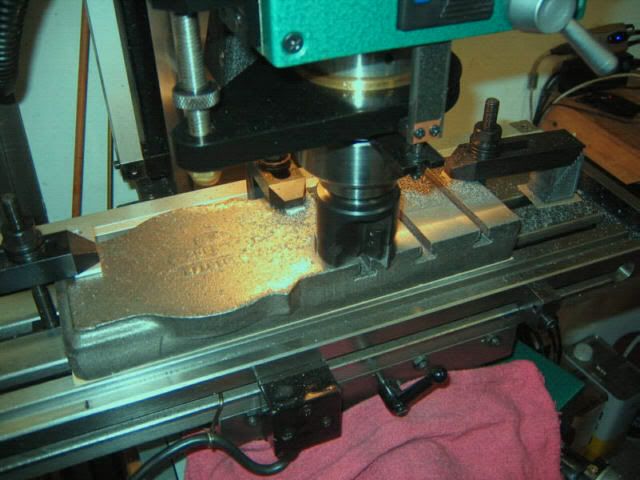
The bottom surface is accomplished in a similar manner. Long before this point, I had devised a cardboard shroud for the mill table, to help contain some of the carbonaceous swarf spewing from the cutter. Here is a video showing the operation, and also giving an overall view of the cardboard shroud, and the general layout of the area:
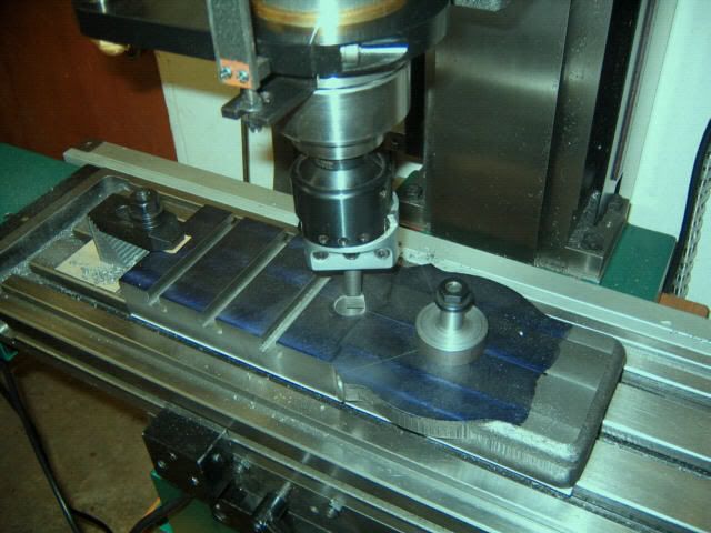
The top and bottom surfaces should initially be machined to within 15-20 thousandths of finished dimension. It’s a good idea to then let the casting “rest” for a day or so, to allow any residual stresses in the casting to relieve themselves before finish milling to final size. My casting showed no warpage at all, resting flat and even on the surface plate.
(to be continued...)
1) The t-slotted cross slide, with its substantial horizontal working surface, makes possible certain boring mill-type operations on the lathe. Accordingly, it facilitates between-centers, or "line boring" operations.
2) It provides for the use of a rear-mounted toolpost.
3) It enhances the usability of a milling attachment, in that the attachment can be mounted at several locations along the cross slide, in addition to the usual compound rest position. If you already own a mill, even a quite large one, there is still no denying the handiness of the milling attachment for machining the ends of long workpieces, as the z-axis clearance of any lathe is essentially unlimited. (Metal Lathe Accessories also offers an auxiliary milling attachment base kit for mounting the attachment at locations other than the compound rest mounting hole.)
4) The S-4382’s dovetail ways extend the full length of the slide, and, provided you machine a new gib of corresponding length, provide an arguably more substantial, and longer-wearing guiding arrangement for the cross slide. Also, due to its larger dimensions (both length and width), this slide offers better protection from swarf contamination of the sliding surfaces. The stock “duckbill” extension of the SB slide is particularly onerous in this regard, as bits of swarf migrate underneath the duckbill. Inaccessible, they remain to become trapped between saddle and cross slide, unless the entire cross slide is removed to clear them out.
5) The semi-circular “wings” which surround the mounting hole for the compound slide are slightly larger on the S-4382, providing ample room for radial index marks at the four polar locations. Having index marks at these additional locations greatly simplifies setting up the compound at various odd angles.
6) The t-slotted surface provides a handy place to set your can of cutting fluid whilst machining operations are underway. (Well, it does.)
7) It’s a fun machining exercise, and the finished slide looks cool.
As with all of the Metal Lathe Accessories kits I have thus far machined, the S-4382 kit proved to be of excellent quality. The machining instructions and drawing are clear and concise, and the casting machines beautifully. Also, while the S-4382 cross slide is intended for the 9”/10k lathes, at least one other forum member has machined an S-4382 for a 10L.
Many of the MLA accessory kits, with a bit of ingenuity, can be machined completely on the lathe itself -- no mill required. Unfortunately, the S-4382 is not one of them. You don’t need a large mill -- the cross slide project fit handily within the work envelope of my SX3 bench mill -- but you need to at least have access to one. If you don’t, you may want to consider having one machined for you. Earl Bower, of Bower Machine, offers the service at a reasonable cost, though I do not endorse his packing methods (see this post).
As always, keep in mind that there are many methods to accomplish the same result, and this account is just one builder’s approach. I welcome any comments on the methods used here, and am more than glad to hear about how others have done it (or would do it.) Also, this report will be presented in multiple, discrete posts as time permits, but feel free to add your own comments in the meanwhile.
Here are some pics of the raw casting. The first is from the top side, after I cleaned off some of the high points with a file. Note that the t-slots are cored to rough undersize dimension, to facilitate their machining:
And here’s the bottom side, showing where the dovetails will be machined:
Machining Top & Bottom Surfaces
For machining the top and bottom surfaces of the casting to rough dimension, I clamped the casting to the mill table, after placing a thin piece of card stock material between table and casting, as a clamping pad. I used an indexable carbide end mill (APT #EM20-R8 “Tri-Dex”), which worked very well, as the “skin” on cast iron can wear conventional HSS end mills fairly rapidly. Here’s a view of the process:
The bottom surface is accomplished in a similar manner. Long before this point, I had devised a cardboard shroud for the mill table, to help contain some of the carbonaceous swarf spewing from the cutter. Here is a video showing the operation, and also giving an overall view of the cardboard shroud, and the general layout of the area:
The top and bottom surfaces should initially be machined to within 15-20 thousandths of finished dimension. It’s a good idea to then let the casting “rest” for a day or so, to allow any residual stresses in the casting to relieve themselves before finish milling to final size. My casting showed no warpage at all, resting flat and even on the surface plate.
(to be continued...)
Last edited:


")