What's new
What's new

Fitch Williams Converter Design & Balancing Instructions

bnelson

Stainless
Joined
Dec 11, 2002
Location
Carmel, Indiana, USA
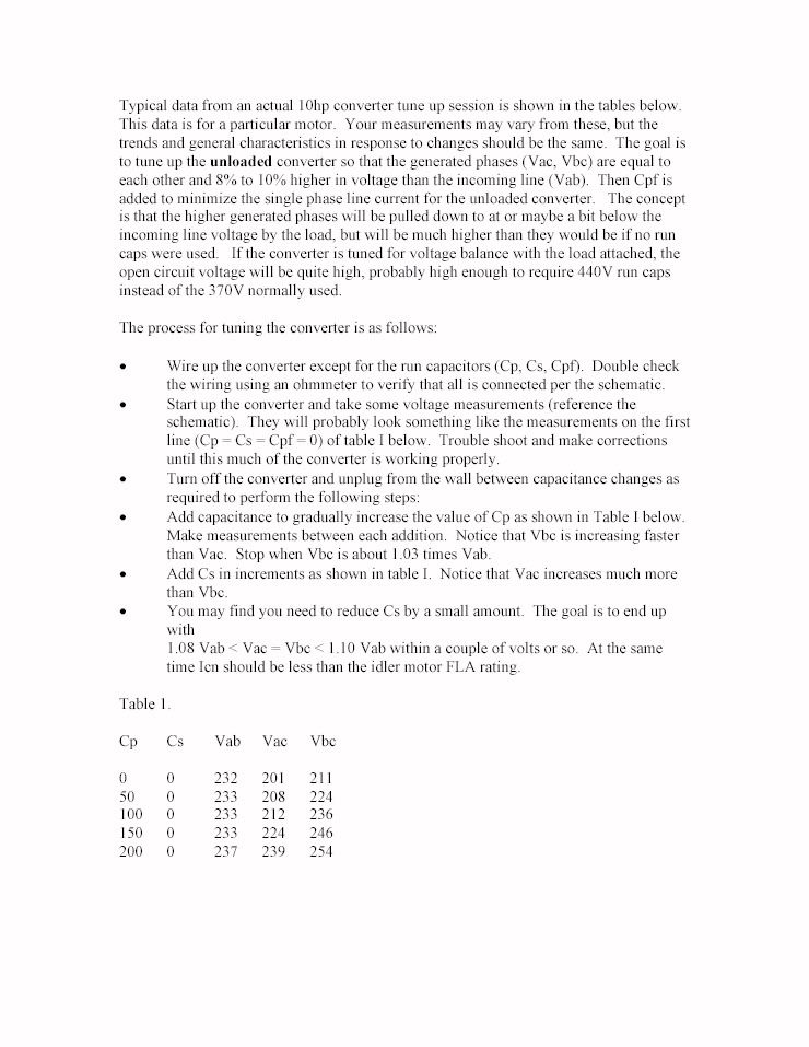
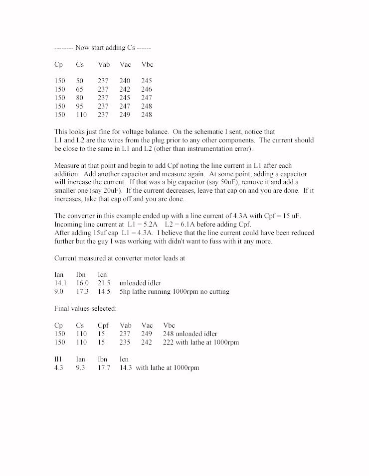
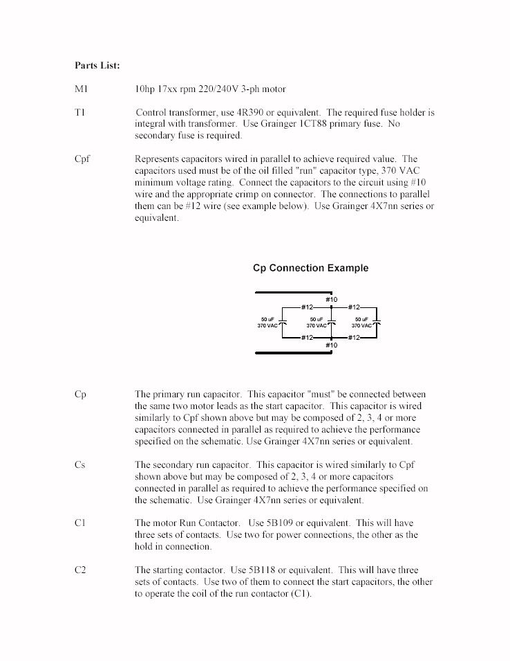
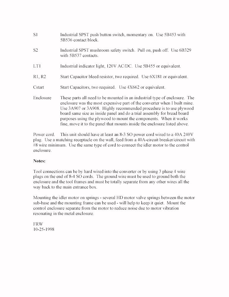
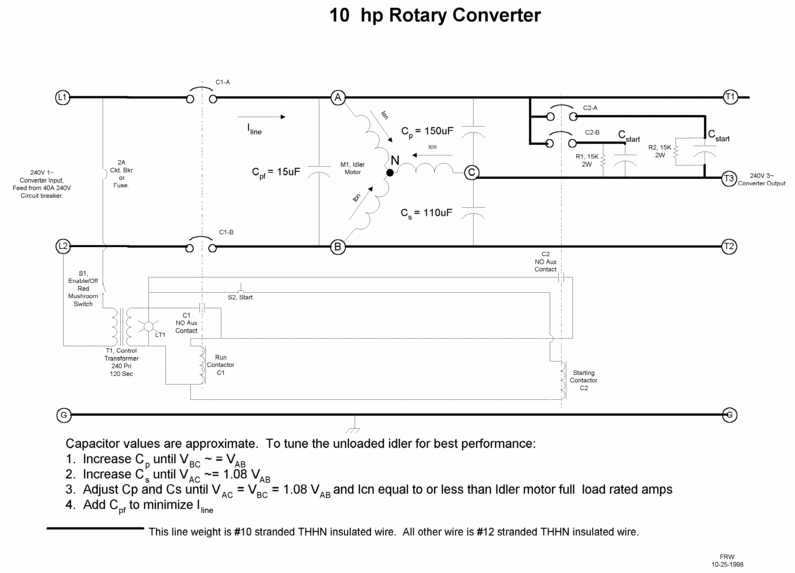
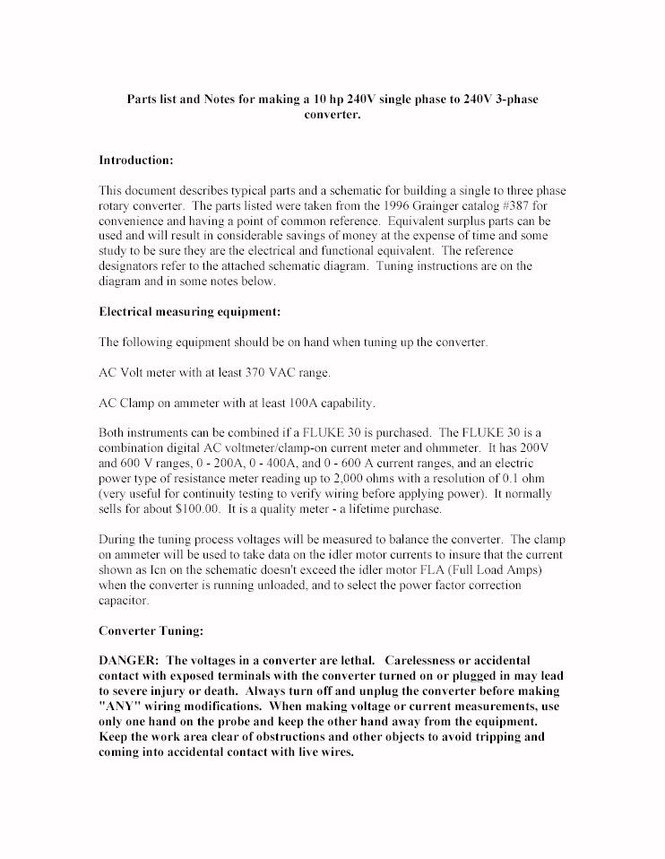
Fitch Williams, who has influenced the world of phase converters with his own design and balancing method, has provided Practical Machinist with the following documentation of his approach.

I will add that we are indeed most fortunate to have Fitch as one of us!

[These image files are OK for viewing here, but do not print well at all. In the next week I'll have a complete pdf file of all this in one concise document which will print out much better.]


FitchWCon.gif


fitcht01.jpg


fitcht02.jpg


fitcht03.jpg


fitcht04.jpg


fitcht05.jpg
 
Fitch,
Cool! I think the modifications you have added to your original schematic are actually from my design way back when. It had the lighted mushroom switch, etc, etc. I'm certainly not trying to take *any* credit, don't get me wrong. I just think it is kind of neat that the mods actually made it someplace! You were an amazing amount of help and an inspiration.

The mushroom switch was a surplus item from Florida, for those that want to know. It is lighted. You PULL it to energize the circuit. They you push the start button. In my case I added a time delay relay which would control the starting cap contactor. The benefit of this is that you have a repeatable time the cap is in the circuit. This was nice for me too because my idler was outside in a dog-house where I couldn't hear it well. Finally, the time delay relay meant that even if you pushed the start switch again, the starting contactor would not fire. The mushroom switch's light would, of course, be ON so that you could see everything was running.

An alternative to the time delay relay would be a potential relay that identified when the third leg was LIVE. I just didn't have one of these.

The phase converter worked *really* well, for those that want to know. It is now owned by another member on this group. The *only* reason I got rid of it is that I couldn't use it with my finiky CNC lathe; I went to a Phase Perfect. As it turned out, however, I had the same problem (premature shut-down) with the PP unit until I figured out how to slow the acceleration ramp on the machine. I probably could have used my trusty old Williams converter on my lathe just fine.

Thanks again, Fitch, for all your help those many years ago! Have you kept track of the number of people you have helped? I'm willing to bet it is staggering... Again, thank you, thank you, thank you!


--Alan

P.S. The converter I'm talking about was posted on this NG. I don't think I ever posted pictures of the control box (I have them, but I don't have a hosting sever :( so I am a bit out of luck), only the "dog house" that provided cover for the motor. That thread is:

http://www.practicalmachinist.com/ubb/ultimatebb.php?ubb=get_topic;f=3;t=000349#000006
 
Alan,

Tell me more about those red pads under the idler. I build large converters, and my most recent had a 22 pound sheave on the shaft for a flywheel, and for pony starting. That sheave adds vibration noise.

I'm looking for a good general way to reduce this noise.
 
I'm using hockey pucks under my RPC and my friend's also, and they work really well. His is bolted to the floor with the puck between the feet and the concrete, and mine free floats. Both setups are nice and quiet. Another thing that would probably work is sandwiching the feet of the idler in between 2 pucks, and drawing them down until they just buckle. Then, the motor can "float" in the mounts. At less than $1 each, you can't really go wrong. I can't remember where I got the idea for the pucks, it was either here or on an old tractor message board. I'm also told they work well for motor mounts in cars too....

Nick :cool:
 
I wish I could tell you more about the pads, but unfortunately I don't have the converter anymore (although I know the person who does... and he is probably reading this post) so I can't look at them. I can tell you what they were like, how well they worked, etc, etc, however....

I bought the pads from one of the (sadly) now defunct local surplus houses. They are quite nice because they area total isolation pad. This means that a different bolt is used to mount the motor and to mount the pad to the base. A rubber puck connects the two parts and thereby makes a complete unit.

The rubber in the pads was less dense than a hockey puck (interesting idea), and I suspect better for vibration insulation. A 5HP motor doesn't weigh that much, so a fairly soft rubber should work fine. Manufacturing your own isolation pad really shouldn't be all that hard; it won't be in as small or as attractive package as the ones shown in the photos though....

When I was done with the phase converter setup shown, I could just barely hear the motor when it was on. Incidentally, the motor was essentially new when I got it. When I ran it with true 3 phase it purred like a kitten. When run as an idler it hummed a bit more, hence the installation of the pads.

Hopefully this information helps describe what I used....

--Alan

P.S. Nick, I got a chuckle with your hockey puck idea... I am in California so we don't have those things floating around everywhere! :D
 
Large rubber stoppers make excellent vibration
isolators under motor housings.

I'm not going to stick that same darn photo up
here because folks are no doubt sick and tired
of it by now - but anyone who wants to see one
way to do it, look here:

http://www.metalworking.com/DropBox/_2000_retired_files/Conv.jpg

Hockey pucks would be kind of hard for the
application. Surplus rubber stoppers work great,
but a quick perusal of a supply catalog like
McMaster Carr or whatnot will give about a
dozen options for quieting down a system like
this.

Fitch, a pleasure to see you here. I've nearly
given up on usenet's rcm at this point.

Jim
 
bnelson wrote "Tell me more about those red pads under the idler. I build large converters, and my most recent had a 22 pound sheave on the shaft for a flywheel, and for pony starting. That sheave adds vibration noise.

I'm looking for a good general way to reduce this noise."

You might look up the old military vibration isolators. We used them for shipping fairly heavy electronics boxes to and from the cape. They look like and are a horizontal coil of wire rope - looks like 1950s front car spring on its side with a metal rib bridging the coils top and bottom. They are simple as dirt and work quite well. Sometimes they are available surplus.

Fitch
 
Wrench (AKA Alan) wrote: "Thanks again, Fitch, for all your help those many years ago! Have you kept track of the number of people you have helped? I'm willing to bet it is staggering... Again, thank you, thank you, thank you!"

You are most welcome. It was my pleasure.

Fitch
 
Fitch...
Have you moved? You used to be in the Lancaster, CA area as I recall. I see now that you are in PA. Did you retire?

--Alan
 
would the above wiring diagram still work if you used a definite purpose contactor with a coil of 220v INSTEAD of the 220volt transformer??

(just trying to redesign based upon my scrap parts.. )
thanks
david
 
"Have you moved? You used to be in the Lancaster, CA area as I recall. I see now that you are in PA. Did you retire? "

Fitch is building his retirement home in PA.

He announced his retirement some time ago on the Wreck (rec.crafts.metalworking).
 
Here is a link to the Fitch Williams document shown above. It is in pdf format, which prints very nice.

WARNING!!! This file takes A **LONG** TIME to load on your computer, as the graphic at the beginning of it is huge. Be patient, and it will load.

It will load much faster if you right-click on the link above, and 'Save Target As' on your hard drive. Then double-click it to load into Acrobat Reader, which bypasses the much slower Internet Explorer plug-in.
 
I just want to say thank you to Fitch and others who have shared their knowledge about RPC and fine tuning. I am new to Practical Macinist but have been following some of the discussions for years.

Recently I purchased a really cool dust collector (built back in the '60) 5Hp and of course 3 phase. Following Fitch's and others advice I was able to get this great machine up and running, which made me feel good about my $75.00 purchase (yes, I only gave $75.00 for this great machine). I'm going to guess I spent another $60-$70 in electrical parts to build the controls.

Not sure how to post photos, but here are a few links:

http://sphotos.ak.fbcdn.net/hphotos...03755035_100001123696402_314963_6649782_n.jpg

http://www.lloydprins.com/pix/controls1.JPG

http://www.lloydprins.com/pix/controls2.JPG

Again, a sincere thank you to all who share their knowledge and talents here. I for one have benefited in a HUGE way.

~ Lloyd - Tulsa, OK
 
I grabbed some old polyurethane skateboard wheels to use for mine when I build it. They come pre drilled with mounting holes. I believe them to be the perfect consistency for the usage. The softest ones I've found are called "Kryptonics". You can find them in varying widths as well. Hope this helps.


Back
Top