GP Tech
Cast Iron
- Joined
- Jan 23, 2015
- Location
- Port Macquarie, Australia
Follow along with the video below to see how to install our site as a web app on your home screen.
Note: This feature may not be available in some browsers.
That's awesome... So how much for some chips?View attachment 194102
Sorry for taking so long getting back on this, I've been flat out like a lizard drinking.
It looks like it has worked, here's an output from fusion360 I uploaded to the qt8. I don't know if the cam post is right though. It was one I found for the mazak T2.
View attachment 194107
What is needed?
1, The eprom chips
2, Parameter change? (bit 7 at OP12)
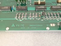
3, Install a FX17 board.
Thats it?
Do you have the EIA/ISO manual?
http://hagstromsystems.se/_Files/MazakQT10N1986ProgramingManual_MazatrolCam_EIA-ISO.pdf
Yes, I downloaded it when you put the links up last time.

That's it.
the post I used came up with a BLUE message "176 start cycle in command display" I googled this but found no reference.
I only played around with it for a few minutes before leaving.
This is the post I used.
Mazak T-plus post processor... - Autodesk Community
I think the penny just dropped, I need to have the screen in the position screen for it to work. Is that right?

I have some questions on the FX17 boards.
These have a DB-25 port, but I assume they are a standard serial communications interface?
Are they RS232 or RS485?
Is there any concern on which version FX17 board should be used?
I just purchased this FX17C board (it looks like it is a revision D).
Warranty Mitsubishi Meldas Control Board FX17 FX17C BN624A328H1 | eBay
View attachment 194205
I don't know what the differences are, I would expect them to be the same and revisions would be just updates.
It's a standard RS232 port, I don't know what the blue connector is or does.
I set the baud rate to 4800 on the nc link software and used the same cable I use for my mori mv-40b fanuc 0m
Thanks, that simplifies things. I have a working RS232 setup for the Fanuc 11M control on my Kuraki mill.
Like ManualEd pointed out, this is a very cool accomplishment.
Two guys from across the globe pooling resources to come up with a solution that works. So cool!
the question now is what other "software" options could we possibly access? I already suggested that rigid tapping (synchronised tapping i think it's called on mazaks) might be doable.
Well if someone has that option on there T2 machine then it should be doable, unless there is a difference in the hardware side, like different encoder.
That post I linked to is no good, it's for a later model integrex or similar.
It looks like the generic fanuc post is a good place to start.
I was making progress on worked and what didn't and my spindle drive or motor took a crap. Really frustrating.
I might abandon the mitsi freqrol and go with a cheap inverter spindle drive.
My spindle is working ok after being left off overnight. The drive doesn't like getting warm after being on for a few hours.
You can check the main stuff in those drives with a DMM.
The stuff that is likely to fail in the high current portion of the drive would be:
Main Rectifier diodes
DC Link Capacitors
Transistor Modules
Wire-wound resistors
You can check all of that with a quality DMM, even without a spec sheet.
Just be sure to check for high DC voltage in those big capacitors before you do ANYTHING else. They can store upward of 600 volts.
Make sure the cap is close to the value printed on the label in uf.
Make sure the TMs are relatively close to each other in their resistance values between E, B, C terminals.
It is tough to get good readings without taking out the bus-bars, etc.
That's where your digital camera will save you. Take good pictures before pulling anything out.
If one of those parts is failing softly due to heat, you can swap in a new component before it goes completely and burns up other stuff.
You might be able to save that drive with some inexpensive parts.
If you know someone with a megger, disconnect your spindle motor and check it too.
I've saved a Fanuc spindle drive with a $10 resistor.
Notice
This website or its third-party tools process personal data (e.g. browsing data or IP addresses) and use cookies or other identifiers, which are necessary for its functioning and required to achieve the purposes illustrated in the cookie policy. To learn more, please refer to the cookie policy. In case of sale of your personal information, you may opt out by sending us an email via our Contact Us page. To find out more about the categories of personal information collected and the purposes for which such information will be used, please refer to our privacy policy. You accept the use of cookies or other identifiers by closing or dismissing this notice, by scrolling this page, by clicking a link or button or by continuing to browse otherwise.
