What's new
What's new

Advanced c.1820s Machine Tools in Close-up

I have seen marks like the planer marks in the photo above on flywheels machined on a vertical boring mill and I assume they come from the gear drive. The cone pulleys look newer than the lathe. They look almost too thin for the foundry practice at the time. Leather was often riveted to a pulley to increase friction but not often to give a crowned surface but it might have been done for that reason.
 
Bill,

An interesting thought about foundry practice. It got me thinking, or more usefully, looking, and I came up with these:-

JD Blockmaking02.jpg JD Blockmaking01.jpg

Pulleys on the Maudslay/Brunel/Bentham block making machinery from Portsmouth Dockyard, now in the Science Museum, completed in 1808. First photo also shows that they were using crowned pulleys by that date.

Thinking about the leather bands on the Fox lathe pulleys, and them only being on the large diameter pulleys: I don't know how fast they were running, but could it be that centrifugal force was reducing the contact pressure such that there was just not enough friction with leather on steel??
 
My thought was that while the small pulleys are 'there', maybe they found that the larger range was most usefull for the work they were doing, so those were leather covered. But I dunno, the smaller pulleys probably get less belt 'wrap' and thus, wouldn't they need more grip?
My greatgrandfather was an inventor. He took over the family business from his father, a small textile mill in Walpole, Mass. He had several patents for improvements to the process of making cotton bandages. Later sold to a partner, Kendall, who took the business further. I would have loved to see that place in motion in the 1800's! J
 
Asquith,
Flat belt drives in the late 1800's were run as high as 5000 feet per minute, I would guess that that lathe would run at one tenth that speed. Maybe they just needed to put a crown on the pulleys and the smaller pulleys tracked well enough and didn't need to be crowned.
It looks like that foundry work was as good in 1800 as it was in 1850.
 
Bill,

It seems that Fox had his castings (All? Most?) made by Morley Park Ironworks. Source (1829):-

The Mirror of Literature, Issue 365.

Two blast furnaces have survived, dated 1780 and 1818.

Photos and information here:-

Photographs of Morley Park User Album

Morley Park Information and Photographs

Picture the Past

They evidently used fine facing sand in their moulds, showing up any lack of finishing in Fox’s patterns:-

JD Fox Bham19.jpg

This shows where a leather fillet was used on the pattern. Not applied as carefully as it would have been on an exposed area! This was on an unseen area of the bolted-on support legs:-

JD Fox03.jpg

When I post photos of the James Fox planer, I'll show an example of a poor quality casting.

Finally, it looks as though the square part of the square shaft was not machined after forging, just touched with a file:-
JD Fox01.jpg

The round parts of the shaft were machined, including the integral collar.
 
Last edited:
Planer, but not as plain as I'd wish

In addition to the lathe, the Birmingham Museums Collection Centre has a planer by James Fox of Derby. Officially it’s 'attributed to' Fox, but I'll aim to remove room for doubt.

Like the lathe, it came from the 1817 workshop at Milford Mill in Derbyshire. The date of the machine is unknown, but it is surely the oldest large planing machine in existence (a small Richard Roberts hand planer dating from 1817 has been preserved).

The machine is in pieces in the Collections Centre, and I only took some quick snaps, so we’ll have to use our imagination to some extent.

There’s a good photo in W Steeds' A History of Machine Tools 1700 - 1910. I can’t reproduce that, but there’s a lower resolution version in Tools for the Job by L T C Rolt. As the book is available online, I'll reproduce the photo here:-


Source:-
Tools for the Job

It will be seen that the uprights don’t look very rigid by later standards, and some of the smaller castings look distinctively flimsy.

The main table slides on one V and one flat way. This table supports three sub tables, which can be positioned as required. They are located on V guides.

The main table is worked by rack and pinion, although I didn’t see the rack.

Note the worm and wheel at the end of the bed. W Steeds says that this rotates a shaft running the length of the bed, and a pinion is fitted at the middle of the shaft. This meshes with a short rack in a vertical guide. The rack has a shoe at the top which bears on the underside of the rack. ‘It has been suggested that this arrangement was used to lift the table when it had stuck after a spell of idleness’. Intriguing.

Some photos of the bits and pieces will follow, accompanied by regret that I didn’t read up about the machine beforehand, so that I might have known what to look for.

Also, it's evident that some minor components are missing in the above photo, making comprehension more difficult.
 
JD Fox Planer21.jpg

You may lose your balance looking at this photo. The uprights are lying on the floor, but I’ve rotated the photo to render the uprights upright.

Now here’s a strange thing. The cross beam sits against the face of the uprights, and gets bolted thereto, but it is otherwise not guided by the uprights. It seems that for the cross beam to stay horizontal, reliance is placed on the two elevating screws. This places a big demand on the accuracy of their pitch, and on the quality of the gear train. Odd, eh?

JD Fox Planer08.jpg
I suspect that the square recessed thing is the head of a clamping bolt. It would have to be removed occasionally when elevating the beam, because of the stiffening ribs in the uprights which mar the free passage of the bolts.


JD Fox Planer09.jpg JD Fox Planer10.jpg

Well-made vertical slide, with clapper box. The slide can be rotated +/- 24 degrees. 24? Why not 30, in case you wanted to machine the V-ways for a Fox lathe, say, whose angle is 60 degrees. Still, the pointer is nice.

JD Fox Planer07.jpg
You can just see a joint line on the curved part. No gib strips, so it looks as though the fit of the of the dovetails is adjusted in the same way as on the lathe, i.e. release the clamp bolts, apply the side jacking screws, tighten the clamping bolts.
 
Feeding time

It might be argued that some of that craftsmanship was an indulgent waste of time and money, but then again, the same criticism could be levelled at some machine tools made very much later. I’m thinking of the showroom appeal of, say jig borers of the 1960s.

It's sobering to think of the earlier work being done in badly-lit buildings with primitive equipment, though.
…………..
Looking now at the automatic cross feed mechanism:

JD Fox Planer23.jpg JD Fox Planer24.jpg

The close-up shows the ratchet pawl. The two gears are offset by half a tooth pitch, doubling the number of clicks per rev without having small gear teeth. Doesn’t look as though the pawl would span two teeth......?

It will become apparent that I don't understand the working of the feed mechanism.
 
Rolt feed.jpg

I have the advantage of higher resolution photos, and I'll have to ask you to use your imagination.

In the enlargement from the photo in Rolt’s book, note the (square) vertical rod on the right hand side. This has some sort of striker arrangement whose height can be adjusted according to the height of the cross slide. This will work the ratchet feed.

On the LHS, low down, note the inclined lever. This is evidently pushed by an adjustable striker on the work table. This will rotate a horizontal shaft, on the outboard end of which is another lever, carrying a roller whose position can be adjusted. This roller strikes an adjustable arm attached to the vertical square rod, lifting it up, and thereby working the cross feed mechanism.

JD Fox Planer25.jpg JD Fox Planer26.jpg

The thumbnails show the levers, shaft and roller, the shaft being fixed in a bracket which would be bolted to the bed of the planer.
 
JD Fox Planer16.jpg

This photo shows the square vertical shaft mentioned above, and the bracket which supported the top end. This can be seen in the 'Rolt' photo in post #26. A thin, delicate looking casting, whose survival intact says a lot for the foundry and/or the care taken during handling!

The movable rack is also shown in the Rolt photo, serving no obvious purpose. I wonder if it would have worked an automatic downfeed for the vertical slide? Note that on the cross slide beam there is an unused lug which might have been associated with such a mechanism.
 
JD Fox Planer27.jpg

I’ve been zooming in on areas of photos, looking for clues.

In post #31 I mentioned the 'movable striker' for working the cross feed ratchet (it strikes me that the foregoing sentence would cause most readers to switch off at once. I’m reminded of the cartoon with a dog looking intently at its master and hearing '…blah blah blah Rover blah blah….’).

Where was I? I think the movable striker is actually the rack seen at the bottom of this photo. I further think that what might be happening is that the rack engages with the inner gear wheel, which rotates freely on the leadscrew. The ratchet pawl would be attached to this gear wheel, while the pawl itself clicks on the outer gear wheel, advancing the leadscrew. Nothing to do with teeth being displaced by half a pitch. That must be coincidence.

As for the flat belt pulley, I'll come to that later. The slender shaft with the pulley, well, that had me puzzled. However, I noticed that the top spoke is recessed and has two holes, as though to receive a lever. Rather like the thing on the front left of the Fox lathe. I don't know what that did either, but suspected that it was for engaging the belt drive. So might it be on the planer.
 
JD Fox Planer29.jpg

I think what we're seeing here is the rack and pinion said to be for raising the table. The assembly had been unbolted and lowered to the floor.

I wonder if the bed was raised in order to periodically apply oil? There's a number of these things in the bed, presumably plugs for oil holes?

Plug.jpg JD Fox Planer28.jpg

Smaller versions are found on the Fox lathe, e.g.:-

JD Fox Planer30.jpg
 
the French engravings in post #7

Old engravings such as these, the ones in Rose, etc., are works of painstaking art, usually by forgotten men, that always stop me in my tracks. The accurate representation of curved surfaces seen en face - crank handles, gears, conoids - is admirable. The journal name is interesting, too. I'm no speaker of French, but it seems to be a publication of a society devoted to encouragement. Also an admirable thing.

These two machines, and the discussion they have generated here, could well form the basis for a semester course in machine tool history. A fascinating and excellent thread.
 
Asquith,
As always your presentations are great. I, for one, am always interested in that which you post.
Instead of tax dollars going to some idiot peeing in a bottle and calling it ART, I'd rather see those monies putting these relics back into serviceable use, if only for museum and education reasons.
I thank you for myself and on behalf of others (if I can take that freedom) for your efforts to keep these machines from disappearing altogether.
 
Thanks for the comments.

I’ll be referring to some of those French engravings later, when comparing this planer with one of Fox’s smaller examples.

Interestingly, some of the finest drawings came from the remarkable Joseph Clement. Clement deserves to be better known. Like James Fox, he started out making textile machinery (weaving looms). He became Chief Draughtsman for Joseph Bramah, then for Maudslay's. He invented and made instruments for drawing and engraving ellipses, with provision for dividing, ideal for producing engravings of gears and the like.

He also designed and produced very advanced machine tools, including a planer which defies description. In fact it was described and beautifully illustrated in the Transactions of the Royal Society of Arts in 1825, but the description is very difficult to follow. It was a remarkable machine, and one wonders whether Fox’s planer was influenced by Clement’s, or vice versa. 'For more than ten years it was the only one of its size in the London area and ran for many years, day and night, on jobbing work, forming Clements primary source of income.'

Clement was heavily involved in the construction of Babbage's difference engine (Joseph Whitworth had some involvement, too).

All the above comes from a chapter by A P Woolrich in Henry Maudslay & The Pioneers of the Machine Age by John Cantrell & Gillian Cookson.

Going back to the Fox planer, this should surely be on prominent display, as it is almost certainly the oldest powered planing machine in existence, noting the vital importance and belated introduction of planing machines into machine making.

Birmingham’s Thinktank museum is pushed for space. The machine’s natural home would have been in Derby’s Industrial Museum, but that closed a few years ago. The Science Museum it is, then. They have plenty of space, and would have lots more if they turfed out the fairground attractions. In fairness, they do have an early planer on display (Whitworth, 1842), and some of the Portsmouth Blockmaking machines, and various other important machine tools.

Bucking the trend in Manchester's Museum of Science & Industry. Instead of hiding machines away, they recently introduced some into their new entrance hall (1835 slotter by Richard Roberts, a Whitworth planer, and the first continuous rolling mill, by George Bedson).
 
W Steeds' book includes a photo of a fine model of a small Fox planing machine in the Musée des arts et métiers in Paris. The date is given as c.1833. It appears to have a bevel cluster arrangement for reversing the table, as on Fox’s lathes.

The planer at Birmingham does not use reversing bevels. Probably because it would have been out of the question to reverse the relatively heavy table and workpiece using simple dog clutches.

Instead, it had a reversing belt drive. The photo shows the driven pulleys, loose in the middle and fastened either side. They would be driven by a direct belt or a crossed belt (for reverse). The belt shifter loop can be seen at the top of the photo.

JD Fox Planer31.jpg

The pulley shaft drives a small pinion, being the start of a double reduction gear train.

It will get confusing, shortly. Referring to part of the photo from Rolt’s book:-


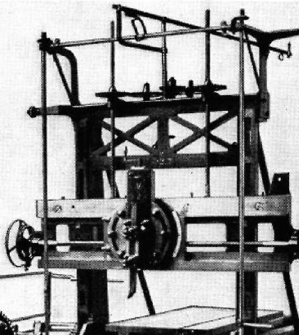
Note the slender horizontal shaft at the top, going from left to right. In the middle is what looks like a letter D, but is in fact a gear sector engaging a short rack (photo below). The rack moves another slender rod fore and aft, i.e. parallel with the axis of the machine's table. Near the far end of this is the belt shifting loop.

However, this means that the belt must be running at right angles to the machine’s axis, which is the wrong way. I’m stumped.

Let’s return to the easier stuff, before stalling again.

Going back to the slender horizontal shaft which operates the gear sector, this shaft has a bevel gear at each end, meshing with bevels at the top of vertical shafts. These shafts both have a short handle, allowing manual belt shifting. The one on the left must also be operated by an adjustable striker on the table. Probably not directly, but via one of Fox’s tumbling weighted levers. A weight is visible in the 'Rolt photo' in #26, but I have no more information about what’s going on over there.

I hoped the 1834 French drawings of a small Fox planer would help, but not at all. It does have a belt shifting system, and tumbling levers, but there the resemblance ends. Link below (note that there are several pages of drawings):-

CNUM - BSPI.33 : pl.580

JD Fox rack.jpg
 
Last edited:
There are a few mysteries concerning chains, etc., which I’ll leave my brain to deal with overnight. Meantime, a few more details……

JD Fox Planer19.jpg

Two of the movable tables which sit on the main table. I don’t know how they were fixed in the chosen place. Each table has just one T slot, and various other slots.

JD Fox Planer33.jpg

On the left, just above mid height of the photo, can be seen the end tooth of the rack under the main table.

JD Fox Planer34.jpg

One of the adjustable strikers. Good long packer under the screw to prevent damage to the rail.


Back
Top