How to install the app on iOS
Follow along with the video below to see how to install our site as a web app on your home screen.
Note: This feature may not be available in some browsers.
Largest Manufacturing Technology Community on the Web
Stay Connected:
You are using an out of date browser. It may not display this or other websites correctly.
You should upgrade or use an alternative browser.
You should upgrade or use an alternative browser.
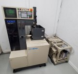
Brother HS-300 on the way
- Thread starter BadTad
- Start date
- Replies 155
- Views 4,217
Got it tucked into its corner and circulating to bring down the conductivity levels. So far so good still have the small seal leak, replacement coming Wed. New check valve here too. Will do both later.
Gotta run work. I guess alingment is next.
Probably will move the resin bottle up front later.
Gotta run work. I guess alingment is next.
Probably will move the resin bottle up front later.
Attachments
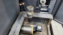
I've been chasing my tail on the alignment of the u/v upper head, first part of the alignment procedure is pretty clear. Move the first axis so the top is going to hit the alignment tool first - do an edge find, upper light will be solid, adjust until bottom light starts to flicker. Same for the 2nd axis. Then, set steps to 5um, jog the wire into the alignment tool and depending on upper or lower light going off first, adjust the top of the head in or out until both lights turn on at the same time.
This is where things get tricky, I'll get a flickering light from top or bottom before I get a solid light on either, I'm not sure if those count or if only the solid light counts. I would assume the solid light, but it does not seem repeatable. I'm probably with in .001 tapper over 4 inches, I don't see why I can't cut that in half, but I've been messing with it for half a day. Anyone got some pointers?
Also, everything is cleaned and stone.
Thanks!
Attachments
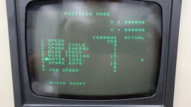
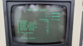
Think I got it within 5-10 microns.. struggle was with the fine tuning.
Book said to set the steps to 5 for 5 micron, but I'm in inches so instead of moving .00019 it was moving .00005 and flickering.
I can get solid on both two lights in one or two steps so that should be about .0004-.0005 taper over 4 inches.
Can't complain I guess.
Book said to set the steps to 5 for 5 micron, but I'm in inches so instead of moving .00019 it was moving .00005 and flickering.
I can get solid on both two lights in one or two steps so that should be about .0004-.0005 taper over 4 inches.
Can't complain I guess.
SeymourDumore
Diamond
- Joined
- Aug 2, 2005
- Location
- CT
Actually, once you get the feel of it, the alignment is simple.
Ignore the upper/lower first stuff.
Jog near the setter, go to STEP and step in .001 increments until one of the lights light up.
Then just loosen the U or V rails and move them until both lit at the same time, all the while STEPping in .0001 increments.
The ignore the ocasional flicker, that just means your are right at the edge of where you need to be.
The way I set it is that one STEP they're both out, STEP closer once at least one is lit the other flickers, STEP closer once more and they both on solid.
The biggest thing is gettin' a hang of the leadscrew and clamp plate as if you look at them in a wrong way, they will move.
Oh thank you, I thought I was gonna lose my mind on this one. I'll try your method in the am to check it, but I'm almost afraid to try and get it any better hah.
Horrible set up for adjusting. My bolts really only work when tightening, soon as I back off they lose all tension and I have to start over.
It feels like there is a spring inside that is trying to keep it underload, but it's gummed up or something. Not ready to open that can of worms atm.
Horrible set up for adjusting. My bolts really only work when tightening, soon as I back off they lose all tension and I have to start over.
It feels like there is a spring inside that is trying to keep it underload, but it's gummed up or something. Not ready to open that can of worms atm.
SeymourDumore
Diamond
- Joined
- Aug 2, 2005
- Location
- CT
Forgot if there is a spring, but they would only work if the whole damned thing is dead clean, which requires complete disassembly of the upper head.Oh thank you, I thought I was gonna lose my mind on this one. I'll try your method in the am to check it, but I'm almost afraid to try and get it any better hah.
Horrible set up for adjusting. My bolts really only work when tightening, soon as I back off they lose all tension and I have to start over.
It feels like there is a spring inside that is trying to keep it underload, but it's gummed up or something. Not ready to open that can of worms atm.
Did it once, and my advise is: Don't do it!
Loosen the clamp bolts so the leadscrew can push the slide past where they need to be.
Tighten the clamp bolts to put tension on the slide.
Start gently pulling in the slide with the leadscrew until the lights are where you want them to be. Use finger pressure to act as the spring ( which may or may not exist )
Tighten the clamp bolts and re-verify the lights.
Rinse-repeat until you get it right.
Well at risk of losing what I had, I redid both axis, and it was a battle but if I held my breath just right and tightened down he clamp screws instead of making the final adjustment (which had the same effect) I managed to get both to repeat touching at the same time or with in 1 button push, with speed set to 10. Putting the alignment fixture in a bag after a spray of oil and I hope I never have to see it again.
Next machine is going to have an automatic cycle for this.")
Next machine is going to have an automatic cycle for this.
Hmm so edge finding is interesting, I can find x and y edges, but not sure how to save them. Center find is dummy proof and what I need to use for now, but would like to figure out the edge finding.. I'll keep at it.
Oh, I think I can hit reset x2 after finding x to zero it, and then find y, but when I hit reset x2 I lose my x.
Oh, I think I can hit reset x2 after finding x to zero it, and then find y, but when I hit reset x2 I lose my x.
SeymourDumore
Diamond
- Joined
- Aug 2, 2005
- Location
- CT
Yes, can be tedious ...
Find X edge
Set STEP to .005, step towards part
Hit RESET twice - X is set to 0
Set STEP to .1, step towards in X
Use JOG to find Y edge
STEP .1 back in X to 0
Set STEP to .005, step towards part in Y
Hit RESET twice to set both X and Y
Once you get used to it, you can use JOG as well and read the position screen how much to jump back in X, that is why I recommend doing a double zero of X.
 Thanks again.
SeymourDumore
Diamond
- Joined
- Aug 2, 2005
- Location
- CT
On AL you can safely assume a .015 kerf, so an offset of .007 should be a good starting point.
That said, with a wire you will likely be within .001-.002 of your finish dimension no matter what material you cut, as long as your offset is set to around .0065.
That said, with a wire you will likely be within .001-.002 of your finish dimension no matter what material you cut, as long as your offset is set to around .0065.
Ok groovy, I just loaded up a plate with bored holes of known value in the machine, setting off the center of the hole(s) and testing a cut and checking with gage pins to see what I get based on offset. I'd like to hold .0005 if I can. Does thickness of material have any play in offset? I'm using a 3/8 plate for testing vs the real 3" part.
SeymourDumore
Diamond
- Joined
- Aug 2, 2005
- Location
- CT
Yes, thickness will have an effect on size, but at 3" height and .0005 won't happen without skim cuts.
plastikdreams
Diamond
- Joined
- May 31, 2011
- Location
- upstate nj
No auto edge find?Yes, can be tedious ...
Find X edge
Set STEP to .005, step towards part
Hit RESET twice - X is set to 0
Set STEP to .1, step towards in X
Use JOG to find Y edge
STEP .1 back in X to 0
Set STEP to .005, step towards part in Y
Hit RESET twice to set both X and Y
Once you get used to it, you can use JOG as well and read the position screen how much to jump back in X, that is why I recommend doing a double zero of X.
Unfortunately it seems to be one axis at a time, but does not keep value.. IE touch X, hit reset twice to zero out (but zeros x and y) then touch Y, but when you zero you lose X.. unless there is another way, book is sparse.No auto edge find?
I just spent a while going through machining data pages in the book to pull parameters for test cutting. Eventually I'll make an .XML database for my cam.
Similar threads
- Replies
- 2
- Views
- 860
- Replies
- 10
- Views
- 887