What's new
What's new

New to me 1997 Kitamura Mycenter 2x

Never seen that screen for tools, I mdi the tool I want ex t3m6 then load and the machine tracks from there… the pot moves but the tool doesnt; 20 holes 19 pots, tool in spindle doesnt need pot so the tool coming out of spindle goes in the pot tool going in spindle cam from but then carosel spins to the proper t spot. For example t1 in spindle, t12(call tool), program running, t12 m6, t1 into pot t12 was in but stores in t1. Hope that makes sense.

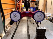
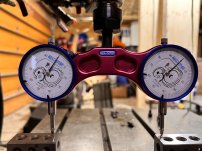
If i read the other guy right we offset similar. I set on one of those 4” dial indactor setters and everything sets off table so my tools never change. Then i use a haimer and measure off blocks 4” to the bottom of my part(could be top if you choose but this way no change between parts as parrallels dont change) then I calculate the diff in height and store in my z update( in offsets)
 
Also If your going to program on fusion I have a post thats decent I could share

Also make damn sure you program a z home before you m6 or you gonna learn🤣

Also ill have to find it but theres a parameter that allows you to split you tool offsets in half from 100(atleast on mine) unspecified to 50 diameter and 50 length, this will drastically simplify your offsets and programming
 
@ALeroyMachinist Awesome writeup thank you for running me through it!

@Lock I will direct message you for the fusion post that would be super helpful. I learned while poking around that Z did nothing during an M6 so I will make sure I have that in my code to bring Z back home.

I understand both of your descriptions, extremely helpful as I learn! But I am missing something fundamental.

An example I want to load these 5 tools (lets say these tools already have H offsets associated with the tool number)
T4
T32
T16
T40
T6

How would I load these tools into the machine? Can I load these from the side directly into carousel and then tell the controller what spot they are in? Or do all need to come through the spindle.

My other experience is in Mach and I just manually load the tool into the spindle (no carousel). So I apologize if this is a very simple question but I cant find anything in the yasnac manual that describes this. Still waiting on the Kitamura manuals....
 
Ok this is what I was missing. Tool number always equals pot number.

So to take advantage of the tool offsets in the machine I would call a H** G43 in my code?

For instance I have a mill for steel in pot one but its offset is saved in H25.

Gcode might be

T1M6
H25 G43

To change to that tool and then set the correct offset?

If this is not the case, I.e. tool 1 = pot 1 = H1 then what’s the point of the 99 available tool offsets?

Thanks!
 
Keep in mind you need some offsets for diameters. If they are not split 50/49 then you will be using a H for your diameter offsets, which can be a little confusing.
 
You can use any tool with any H offset, but as David said above they are shared with the D offsets as well.
 
Thanks for clearing this up. I think the big thing I was missing was that this machine T1 is always in Pot 1 and so on. Now that I know this it is much clearer.

pm4029 D0 changes the machine from shared H and D to separate H and D. I will need to learn a little bit more on this subject for sure.

I need to order manuals for the machine the quote I got back includes
Maintenance Manual
Operations Manual
Parts Manual
Programming Manual

Do I need all of these? Are any of them barely used?

Thanks
Scott
 
I think for clarity you should not worry about the tool pots. They are all the same and will rotate throughout the magazine locations, but the tools will always go to the same magazine location.

I touch all of my tools off of a 1/4" round pin on top of either my vise fixed jaw carrier or tailstock. The advantage to this is Kurt hard jaws are .25" above the fixed jaw carrier so I can put the part in the vise, measure how far above the vise jaw it sits, and input that value into the Z fixture offset. I have the tool measure feature but have only used it once. I find it is faster to touch all of my tools off then load them into the magazine as it saves a lot of tool changes and jogging.

You are going to want all of those manuals. How much they are worth is related to how valuable your time is. Having the manuals will save you a lot of time, and from the looks of your machine, you're going to want them.

I said earlier that you are going to want to go through your lube system and make sure all metering devices are working. The way I did it was to loosen the tube at the meter enough to introduce a bubble then tighten it back up. Now you can watch that bubble move as the lube pump cycles. You can not do this with the spindle air/oil unit. You need to bleed the air out and then set it for the proper amount of oil. My instructions had me do so by turning a screw X number of times for each lube point. I am pretty sure my ball nuts are lubed by the spindle oiler and the thrust bearings are on the way lube system.

You really want to check how perpendicular the spindle is to the table before spending much money. If it is way off you may want to rethink how valuable the machine is to you.
 
@DavidScott you have said this a couple times so before pulling the trigger on the manuals I checked the Z head for perpendicular.

The tram gauge I have is in 0.001 so probably not as good of resolution as I should be but figured it would tell me if something was way off. I ran the test using the same block and same dial indicator on each side of the table. As well as using 2 blocks and both dial indicators. Zeroing both indicators in the same spot of course before rotating the jig. My 123s are also pretty cheap versions so they could be off a bit as well.

Its hare to take pictures of this but the close up here is a good representation of what I saw.

IMG_6965.jpg

I also checked 90 deg from this spot and they were even closer. I definitely dont have alot of knowledge here but I think this is decently perpendicular? Thoughts?

I ordered some new tubing for the way lube system and plan to start going through each connection one by one. I should be able to see new oil going into the new tubing to confirm the metering valve is working on each. Most of the tubing is very brittle so it will be a slow process to trace each one back.

I still cannot get the machine to perform a tool change using MDI. It keeps setting the 007 alarm which is invalid tool number.
If I call
T11 M6
The carousel will rotate to 11 then alarm sets and nothing further happens

I can get it to tool change if I use the dial on the right of the controls
Index to tool I want
Rotate pot down
Tool change
The carousel moves to the old tool number location
Rotate pot up

We were able to perform tool change through MDI before moving the machine. Am I overlooking something simple here?

Thanks
 

Attachments

  • IMG_6963.jpg
    IMG_6963.jpg
    267.4 KB · Views: 6
  • IMG_6964.jpg
    IMG_6964.jpg
    230.3 KB · Views: 7
Your head is good. What we are looking for would be a few thou off the way you tested it.

Have you tried calling for a tool change with single step enabled? That may give some info on the problem. Interesting that you can manually do a tool change.
 
Your head is good. What we are looking for would be a few thou off the way you tested it.

Have you tried calling for a tool change with single step enabled? That may give some info on the problem. Interesting that you can manually do a tool change.
Eh, my machine behaves the same under certain conditions, same error and all, but will do manual tool changes without issue, then will change tools through MDI. I think sometimes the i80 forgets what tool is actually in the spindle, but that's just a guess.

@Scott.Damman try doing a manual tool change first, then do a tool change through MDI,

T01;
M06;

Should do an automatic tool change
 
Alright, I think you guys told me to try this but I didnt totally understand.

If I do
T1 - WR
Cycle Start
M6 - WR
Cycle Start

The machine performs the tool change as it should

If I do
T1 M6 in the same command it will not perform the tool change. What is odd is I am 99% sure we performed tool changes at the previous owners location having the T and M command on the same line. Not sure what would have changed.
 
I think it's just a quirk of the i80, I just tested doing T1 M6 on the same line, and it throws error 7. If you want to have them on the same line just use the EOB button to add a ";" between commands
T01;M06;
WR, cycle start
You can even call the next tool in the same line too if you want
T01;M06;T02;
Handling T and M6 on same line or requiring them on separate lines is determined by how the machine builder wrote their ladder logic and integrated the control to their machine.
 
If I preload a different tool than I want to change to my mill will change to the preloaded tool first, then change to the one I programmed with the M6. So maybe preload the tool you want to change to and exclude calling it again with the M6.
 
If I preload a different tool than I want to change to my mill will change to the preloaded tool first, then change to the one I programmed with the M6. So maybe preload the tool you want to change to and exclude calling it again with the M6.
Yasnac has parameter for that case, how to process such case.
 
Both of my i80 Kitamuras will tool change just fine with it all on one line.
But both of my machines are a few years newer than yours.
 
Some updates

Waiting (impatiently) for lube tubing to come. Found a couple of metering valves that dont seem to be working so ordered those.

I am still waiting on the manuals should come as USB drives. I ended up purchasing all of the manuals. Thanks for the suggestions on this, I am sure I will end up using them.

As I wait for parts, I got a post process file from @Lock thanks for this. I had to modify the tool change to be on 2 separate lines but otherwise the post seems to work. I was able to successfully DNC a file and run it cutting air but a couple things were not right with offsets.

I was able to do tool offset but I am still missing something in the process (operations manual would be handy right now). When I went to tool measurement button the bias was set to -17.xxx. I changed this to 3 to set off a 123 block for now. I brought the head down from Z home touched off the tool then hit retract. The machine recorded a large negative tool offset which did not seem right? So then I set my G54 numbers, I found the left and rear of my stock put those into X and Y respectively. For Z though I dont have a known gauge length tool so what is the process for setting Z? Assuming the G54 is an offset from Z home? Since I was cutting air for this run I put the nose of the spindle at 5 inches off the table and set that as my Z.

So in Fusion I picked the left rear bottom of my stock. I set the coordinate system to x plus to the left and y plus coming at me (same as the machine). Loaded the program and got an error. It was clear the large tool offset was not right. So I manually put a tool offset in. In this case 3". Tried running the program again and the program executed

But... the Z was ~8 inches above where I thought it should be. Also the machine performed the operations mirrored. I.e. in fusion the tool path would have been going to the right on X and it went to the left... I think I must have had my coordinate system wrong in Fusion.

Couple questions, in CAM where do you set your WCS? Which direction is X plus?
Here is what mine looked like.
Coordinate system.JPG

Is the tooloffset an offset from Z home? How is this offset applied to G54 Z?

Thanks for the help here, math is not working in my head so I appreciate any help...
 
Im guessing you defined x,y based on the tag on back of machine and im guessing they were trying to say that when the table travels that direction you are getting a x plus y plus. But Its no different than any other mill ive ran, x plus to right of offset zero and y plus to the back of machine from your offset so flipped from what you have.

I could never figure out a reasonable z offset so I ended up setting off table but at 4" with the dial presetter then using my haimer(you could use a tool) to calculate the difference between my reference point of 4" above table. I leave g54 z at 0 and the difference on the update page which is usually around .3-.5 above the 4" reference.

z offset is measured from z home so -17 doesn't seem all that out of line but maybe? I would make sure your tool offset was on the right tool when measured and verify on the update page of position there's not something in z. This update feature can be SUPER handy or it can just as easily scrap a part and crash you if you forget you have something in it....

I would highly recommend one of those tool setters and a haimer regardless of how your setting tools etc


Back
Top