What's new
What's new

So I bought a lathe....

I have a 1927 Oscar Ehrlich sales catalogue for Drehbanke and other machinery; it shows its age but I believe there are no missing pages and even includes a price list and a photo of a Prazisions-Leitspindel-Drehbank modell A 1 very similar to your lathe.
I have no use for it; if you would like to have it please send me a PM with your mailing address.
 
I Finally taken delivery of the tools needed to take the spindle apart. Here's what I found.

be8fa89a-0262-45ca-8d3f-bc1278d64f46_zpsx9bacm3h.jpg

Missing tooth on the gear that drives the backgears. Stil seems to work ok.

005_zpsryfpcfyq.jpg

Some sort of tape to take up slack?

008_zpsxbuqoxzp.jpg

That gear is really hard to remove :(

011_zps63zso4sr.jpg

Big Journal.

017_zpshsfw0yta.jpg

Inside big bearing. (Is that felt oem?)

013_zpsjwvty3qv.jpg

Small journal.

021_zpsn3dl6dg6.jpg

Inside small bearing.

@RODULU; Thanks for the kind offer but would you be able to scan the document and mail it to [email protected]?
On the lathes.co.uk website it would serve a better purpose than in my dusty archives. Besides, my days a Ehrlich owner could very well be short lived.
 
UberPrutser,

You wrote "I Finally taken delivery of the tools needed to take the spindle apart."

This got me to thinking about the age of this lathe vs. the introduction of "DIN" tool standards. If I'm understanding the dates correctly, almost all the tools you will need will be in the DIN family - for example, you will need a wrench for the spindle's slotted nut. The good news is that this is very likely a standard DIN tool, easily obtained in Europe (or just about anywhere in the world.)

The wool felt oil wick is indeed OEM. Be sure to select genuine wool felt when you replace it. Synthetic wools may not be compatible with spindle oil.

The bearing and the spindle don't look too bad.

I'm unclear on whether there are two small brass shims in the second photo of Post #44. Is it possible that a previous owner added shims because he did not understand the correct method to adjust the bearing clearance?

Good luck with this machine. It seems very well made and certainly can do a lot of work for you after you get it set up correctly.

John Ruth
 
Uberprutser:

Your photos tell quite a lot. Here are some observations:

1. The two pieces of brass shim stock may have been used to get a bit more adjustment on the bearing. The bearing may have worn to a point where the adjusting nuts could not take up the wear.

2. The spindle journals are about expectable for an old lathe of unknown history. I would suggest stoning them with a "hard Arkansas" oil stone. An Arkansas stone is a hard white stone that is so fine you would not think it could remove metal. All you are looking to do is break any sharp crests on the scored ridges on the spindle journals. Ideally, if you could set the spindle up in another lathe and stone the journals with the spindle turning, that would be best. If not, simple hand-stoning, using the stone at about a 45 degree angle to the centerline of the spindle, and criss-crossing it so the whole journal is stone will be fine and is what we do on larger turbine journals.

3. Bearings: these have seen some wear, and the pattern matches the scoring on the spindle journals. The first step is to reassemble the bearings in the headstock and see how much they can be "closed in" using the adjusting nuts. Telescoping gauges and outside micrometers would be the way to check bearing bores against spindle journals. There has to be a reason why that shim stock was used. If some adjustment remains on the bearings, based on mike readings of the journals vs bores of the bearings in place in the headstock, then I'd suggest the following:
-"shave" the bearings using the edge of a lathe parting tool or other straightedge scraper (I grind mine from broken pieces of power hacksaw blades, and stone
the cutting edges). A light "shave", using a drawing motion on the straightedge scraper will clean off the high spots on the bronze and get more bearing
surface. The coarsely scored surface would likely be OK, but my thought is to get more "plateaus" or continuous bearing surface to enable the wedge-shaped
oil film to be maintained between journal & bearing. The continuous scoring looks like it might not allow this wedge-shaped oil film to form properly.

-polish the insides of the bearings using "Scotchbrite" pads. My own method is to take a bronze brazing rod and bend it like a hairpin, pinching a piece of
Scotchbrite pad. I then chuck the "brazing rod hairpin" in a hand held drill and "flap out" bores to polish them up. Not real exact, but it will break any
burrs and blend the scraped surfaces. It will not restore the bearings to like-new finish, but will improve the ability of the bearings to maintain that
wedge shaped oil film once the spindle is rotating in them.

-wash the bearings thoroughly with solvent, blow clean with compressed air, and keep wrapped in clean cloths until ready to reassemble.

4. The broken gear tooth: My own recommendation here is:
-remove the gear from the lathe spindle or cone pulley.
-mill or file the area where the fracture occurred, exposing "virgin iron". Do not use a grinder for this as it will smear the graphite in the cast iron
and create problems for the brazed repair.
-drill and tap two or three small holes along the "root" where the gear tooth broke out.
-screw some long steel screws into these tappings. Screws must not project beyond the root or crest of the tooth.
-Cut the screws off so their tops are a bit below the crest of the tooth
-"cook the gear" with a torch or in a wood fire to burn off any remaining oil or grease in the cast iron. Let the gear cool so it is perhaps 300-400 degrees
F.
-apply flux to the area where the root of the repaired tooth will be. Using oxyacetylene and bronze filler rod, build up material for the new tooth using
brazing. Make sure to get good "wetting" or "tinning" so the bronze brazing metal adheres to the tooth root area on the gear as well as the steel screws.
-build up successive passes of brazing until you have enough "meat" to make a new tooth
-let the whole gear cool slowly in dry sand, ashes, or under insulation
-using files or any other means available to you, shape the profile of the repaired bronze tooth. Using some Prussian Blue and a mating gear to "roll in"
against the repaired gear will show you where you need to file/dress the repaired tooth. A knife edge file and some patience and you can create a new tooth.
It need not be an absolutely perfect or exact profile, as the bronze braze metal will "cold flow" or "cold work" to conform to the mating gear teeth. You
need to get a close fit, and the gear tooth will "work in" once the lathe is run under power. Bronze brazing metal will cold work, and in the process, will
work-harden and get a burnished finish as the tooth "works in" against the other gearing.

That's my suggestions based on the photos.

Regards & Good Luck
Joe Michaels
 
Thanks Joe, you've given me hope again :) When I saw those journal and bearing surfaces I thought, that's it, game over! But now that I've read your posting I've decided to push on and see if I can get this thing running. After all, I've already got a motor and vfd. Also, the new workbench is nearly finished.

I'm going to order a micrometer calliper, I assuming vernier callipers are not good enough.
But I'm having a hard time deciding what kind of stone I should buy. I've read the the Arkansas mines have been depleted and that synthetic stones will be sold under the Arkansas name. There are also different shapes available?
The prices I've seen range from 6 euro to well over a 100. I usually have no problems buying tools but I'm not going to buy a overprices piece of mineral that will cost more than what I payed for the lathe :) Then there are Belgium stone, Japanese stone, Turkish stones.... So some stoning advice would be appreciated. Below is a link to a local reseller. Are any of these good?

Natuurstenen en olie << Slijpen en wetten << Houtbewerkers << Baptist.nl

@SouthBendModel34. I don't know if the machine is DIN compliant but I've bought a set of adjustable hooked spanners because I had a hard time finding non adjustable ones with the right diameter.
 
Uberprutser:

I am glad you appreciate my posts. I looked over the link to the catalog you sent. Pretty easy to understand the Dutch due to similarities to German (I speak a workingman's or farmer's German, learned on jobs), and English. "Wetstenen" is obvious: "Whetstone". I use a small Arkansas stone that is square in cross section, about 18 mm-20 mm x 18-20 mm. The shape of the stone is not important so long as one surface of it is flat. You posted a link from a home-builder's or carpenter's type of supply firm. If you can find a machine shop supply firm, you may do a little better on selection and pricing on the Arkansas stones. The stones shown in the catalog link are "knife edge" shape, more used for honing woodworking chisels and gouges. The lowest cost item in that link was a set of three (3) stones, and that is two more than you need.

I keep a few small oilstones in my machinist chest: India Medium Hard in a few shapes, and Arkansas Hard in just the square shape. It should not matter whether the stones are natural or manmade. The India Medium Hard is manmade abrasive. It is quite a bit coarser than the Arkansas stone, but still is quite a fine stone.

If you come up short on getting the India Hard stones, here is another idea: get some "Crocus Cloth" (at least that is what it is called in the USA). Crocus Cloth is the finest grit abrasive cloth. If you ran your finger over Crocus Cloth, you'd think it was smooth paper and wonder how it cut at all. It has a reddish brown color abrasive. Get a few sheets of Crocus Cloth and a flat piece of steel about 20 MM wide x 100 MM long. Rip off a piece of Crocus Cloth (you tear it rather than cut it with scissors or snips) so that the piece of Crocus Cloth can be wrapped around the piece of steel with no wrinkles. Put a little light oil like penetrating oil or some turbine oil (ISO 46 or lighter) on the journals and use the crocus cloth on the steel bar as you would use an oil stone. You will have to renew the Crocus Cloth from time to time.

Whether you use an oil stone or the crocus cloth on a piece of steel, the method is the same. Work the stone (or the steel with the Crocus Cloth) as if it were a file on about a 45 degree angle to the centerline of the spindle, and keep working it around and along the journal so you do not stay in any one place for more than a stroke or two. You keep working around and along, and you do this until you have knocked off any rough or sharp ridges. My own test is to very lightly drag one fingernail along a journal surface being investigated or inspected. If my fingernail catches anything, I look a bit further and determine if it has a sharp ridge or jagged surface. With an Arkansas Stone or Crocus Cloth, you will not be removing enough metal to measure with a micrometer, just cleaning up the surface. The idea is to create a few more "plateaus" to help maintain the oil film between the journals and the bearings.

For measuring bores, I use what are called "telescoping gauges". These are spring loaded devices which can be placed inside a bore and locked to capture a measurement. I then use outside micrometers to measure the telescoping gauge. I have a set made by Starrett which goes from 1/2" minimum bore diameter on up to 6". The good party is if I am boring and turning mating parts to fit each other, I use the same micrometer. If the mike is off a little (not that mine are off as I have standard bars to check and adjust them to), the measurement is "comparative". No two people have quite the same "feel" or "eye", and while I am not working to so fine a degree of measurement, again, it is consistency. My eye, my feel, same micrometer for inside and outside measurements.

For your old lathe, take things slow and I am sure you will get the oldtimer back to running. These older lathes can tolerate a lot of abuse and wear and still produce fine work. A little time spent getting the bearings and journals cleaned up with a stone and light "shave" (my term for a fine scraping to "take off the whiskers") and you may be quite happy with how the lathe performs.

I was in Amsterdam about 3 years ago with my wife on a short vacation trip. We were limited in our time and what we could see. The result was I did not get to visit any Dutch machinist supply stores. On our last day in Amsterdam, my wife and I visited the Anne Frank House. Afterwards, we walked along the canal and found a cafe (I think the name was something like Het Smalls) for beer and sandwiches. We passed a kind of artist's market and a farmer's market. In that area, there was a contractor's and industrial supply store, but it was already closed for the day (closing early on a Saturday). That might be the kind of place to find the oil stones and Crocus Cloth.

Good Luck !
 
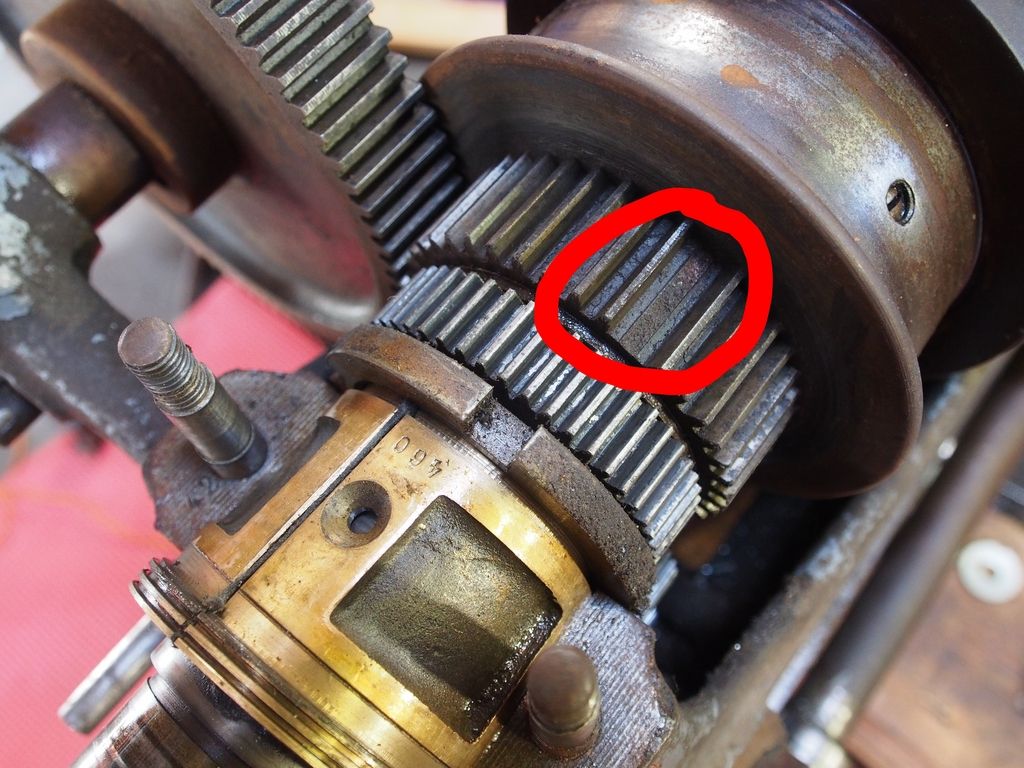
A few comments to amplify those that have been mentioned regarding the broken teeth on the spindle gear.

There are a variety of methods to do this, including the one mentioned (which was to braze up and then re-cut the teeth, using
support pins embedded in the braze).

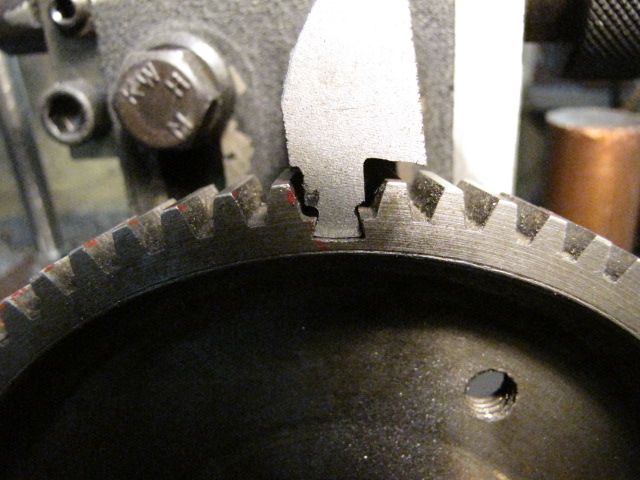
1) Replace the missing tooth with steel pins pressed into the casting, and profile the pins to act as a tooth.

2) undercut the region of the gear with a slot where the tooth is missing, and silver solder in a steel or cast iron
slug, which is then cut into a tooth with an involute gear cutter.

3) fabricate an entirely new gear to replace the one missing teeth.

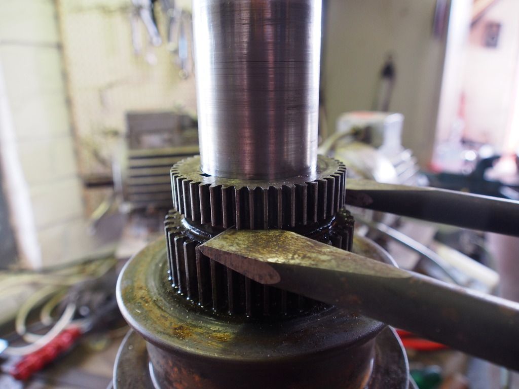
Here's an example from my elderly seneca falls lathe, where the former owner had done the first fix:

SF_gear01.jpg


SF_gear02.jpg


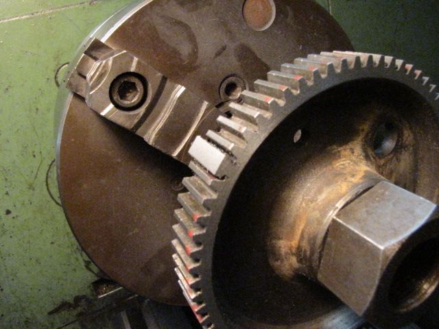
In this case I chose to re-make this gear from scratch as it was not too large, could
be made of steel, and had several missing teeth:

SF_gear18.JPG


The gear that was replaced is the outboard one on the end of the spindle. Notice
the back gear that larger and mounted to the cone pulley, is also missing teeth.

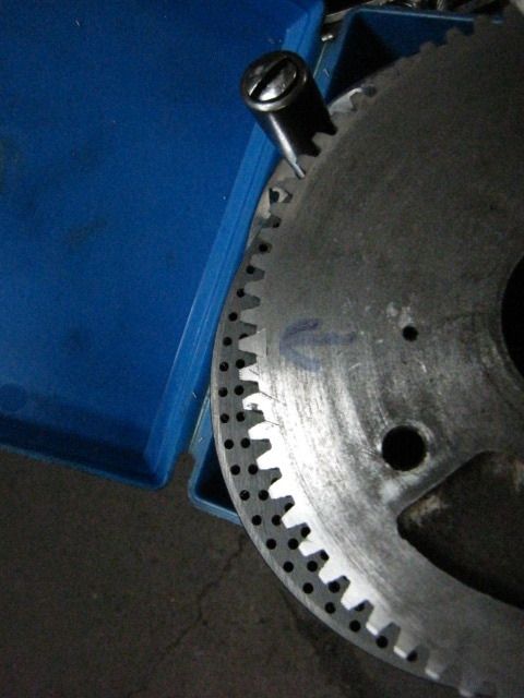
I eventually did purchase some cast iron bar stock and re-made that gear as well, which
was a tougher job as it has a long boss on it that presses into the body of the cone pulley.

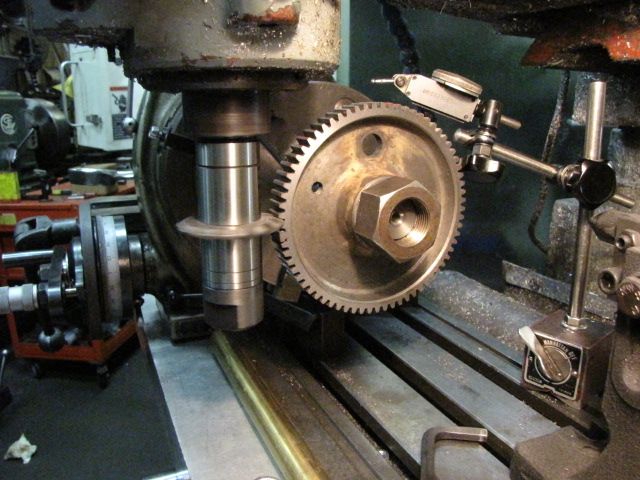
If you have access to a milling machine and a dividing head, it really is not that tough a job
to re-manufacture a gear like this. The involute cutters are a very modest expense if you can
find the one that you need for your gearing system.
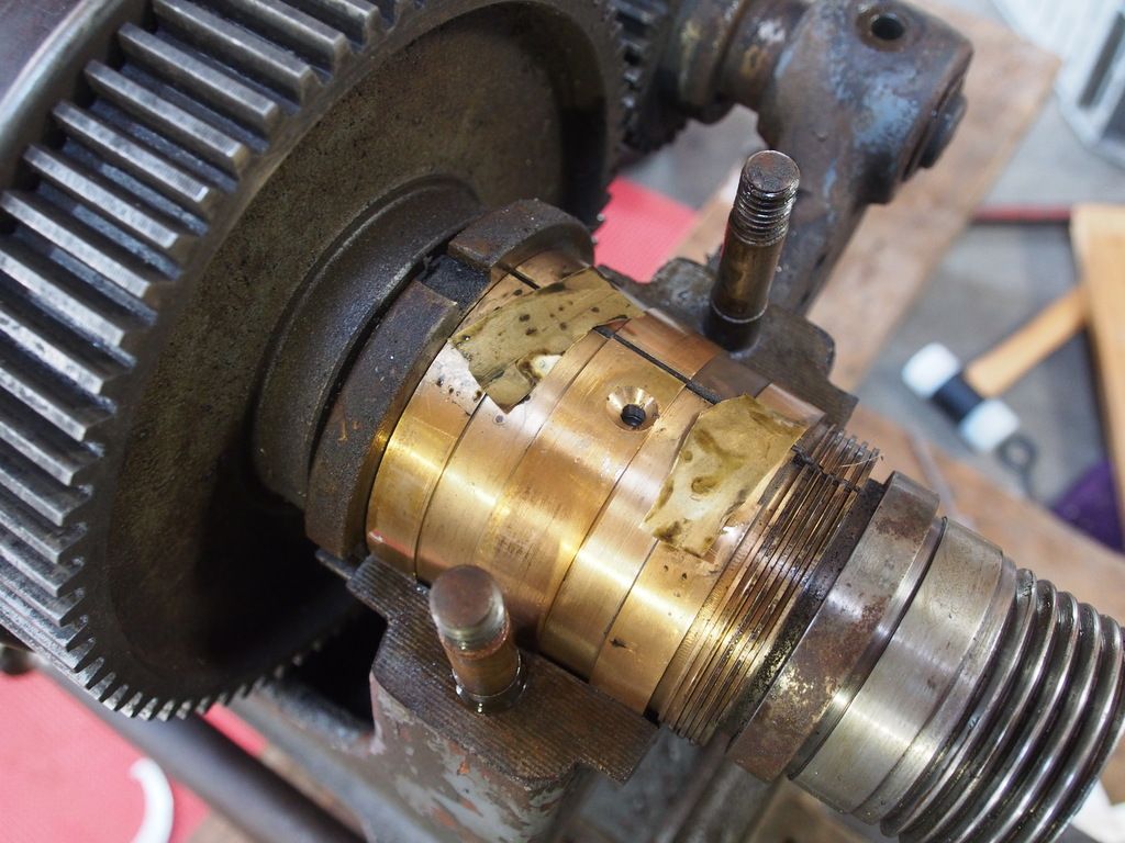
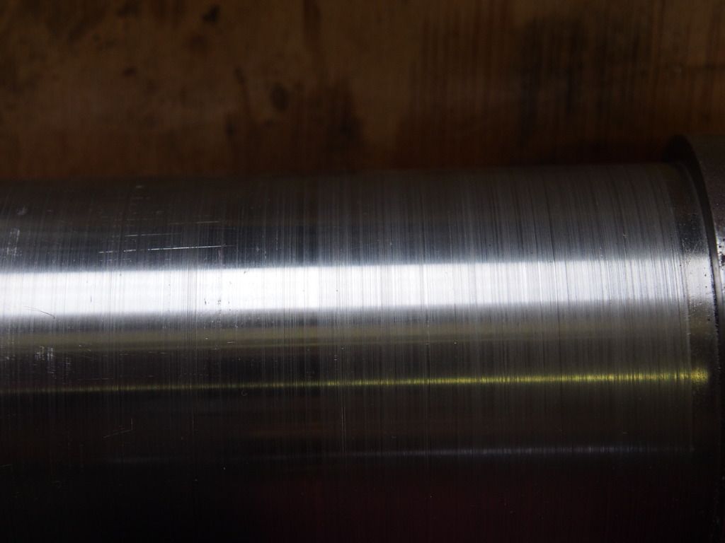
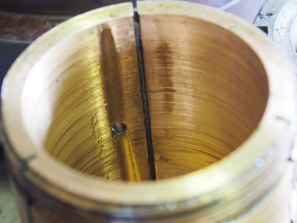
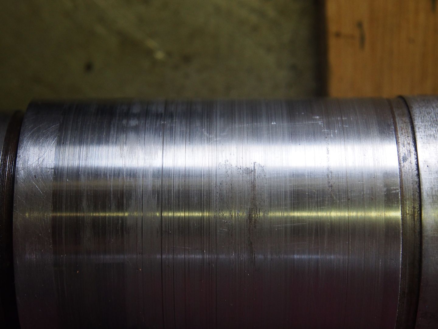
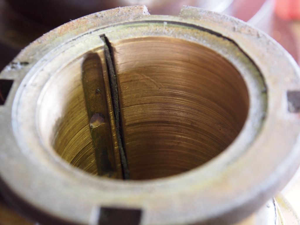
 
I also suggest repairing the gear in some way. With the tooth missing, it may still work, but it puts a lot of stress on the unbroken teeth, so more may break if much load is put on it. Jim's inserted rod teeth will work to ensure that the teeth are properly guided, and can take some strain off the remaining teeth, even if they are not a perfect "fix"..


And, yes, pretty much every journal bearing will look like that after a while. It is not a problem unless much worse, as you have been told.
 
Another method of gear repair that I haven't personally tried, but I have heard several positive reports, even in terms of durability, consists in drilling and tapping ad described above, inserting brass screws, file them to shape (better to err in too small than too big), and form the new tooth/teeth with JB Weld or similar epoxy, using the mating gear as template (interposing some plastic wrap film could be a good idea and allows forming the tooth without contaminating the epoxy with any wax or oil).

Worst case scenario, if this method doesn't hold up in this case, you can always chip the epoxy away, unscrew the brass screws, and continue with one of the techniques described here above.

Paolo
 
There certainly are a lot of ways to repair a broken gear. How about stick welding?
But it's going to be difficult to repair this gear because it look like it's been machined directly on the pulley.
There is no key way. Or could it be shrink fit?
 
Uberprutser:

I doubt that the gear was machined from the same casting as the pulley. There is no room for the "runoff" of the gear cutter. My guess is the gear is probably a shrink fit, and is most likely also keyed to the pulley hub.

The gear appears to be cast iron. I would not recommend stick welding for a repair of the broken tooth. Stick welding means using a nickel-alloy repair electrode. These are generally a bit harder than the rest of the gear, even if the weld deposit is machineable. Nickel alloy electrodes are known as "Ni Rod", and come in various alloys, some of which leave a very hard weld deposit which cannot be machined or filed, and some which leave a softer deposit. Either way, the amount of localized heat that Ni Rod stick welding would put into the gear and the resulting weld are not something I'd feel comfortable with for this kind of repair. Ni Rod is fine if you are repairing cast iron which has broken apart and can take steps to control the weld shrinkage and cooling rate. for a small, precise repair like this gear tooth, unless you are able to oxy-acetylene weld with cast iron filler rods and flux, then bronze brazing is the method I'd use. Bronze brazing is very forgiving process and will give you a fine repair.

I'd get the spindle out of the cone pulley and do a careful inspection of that gear. Using solvent and cleaning things well, you may see a circular "joint line" where the gear meets the hub of the pulley. If you do see that joint line, then the gear is shrunk onto the hub of the pulley. Warm the gear using a torch, and see if you can separate it from the pulley. Packing the bore of the pulley with dry ice and warming the gear, you may not need to use any real force to separate the gear.

Whatever repair method you choose for that gear, it has to come off of the pulley. How else would you shape the teeth ? Using files and possibly a die grinder, runoff room at both ends of the broken tooth are still needed. You are in it this deep, so may as well take the time to see how that gear is fitted and fixed to the pulley.

I am old school about a lot of this kind of work, and using oxyacetylene brazing is something I find works quite well for these kinds of repairs. With a smaller brazing tip on the torch, you can build up passes of bronze and control how the repair is shaped. As you machine or file into the repaired area, if you find things are a little undersized or find a porosity, it is a simple matter to do a little touch-up with the torch.

Years ago, cast iron repair welding was done routinely using oxyacetylene. Filler rods which were square in cross section, made of good gray cast iron were used, along with a flux. I've never done this type of welding. Supposedly, this gave a repair weld which was homogeneous with the base metal and, if allowed to slow cool, gave a good soft iron weld deposit. Cast iron is a funny material to work with when welding. The problem with fusion welding of cast iron is often in the cooling rate. If the weld zone cools too rapidly, white cast iron is formed. This is extremely hard and brittle and unmachineable for all practical purposes. It also creates some bad internal stresses and resulting cracking. Brazing does not melt the cast iron, only gets it hot enough to allow a "wetting" or "tinning" to take place where the molten bronze "latches onto" the iron. The bronze, being fairly ductile, is able to absorb a lot of the cooling stresses. As long as the cast iron part is slow-cooled, brazing makes a good repair. It is usually at least as strong as the cast iron itself.
 
I think it is a cool old machine. If I were you I would start to restore it. What I did with my old Barnes was disassemble everything. All large casting were sandblasted and the machine surfaces and gears were soda blasted. That moved the project ahead quickly and it wasn't expensive! But before you do that make sure everything is working. I had to repair some gears and a rack and pinion. I don't have any change out gears so threads are off the table. Taps and dies are readily available.
 
Another method of gear repair that I haven't personally tried, but I have heard several positive reports, even in terms of durability, consists in drilling and tapping ad described above, inserting brass screws, file them to shape (better to err in too small than too big), and form the new tooth/teeth with JB Weld or similar epoxy, using the mating gear as template (interposing some plastic wrap film could be a good idea and allows forming the tooth without contaminating the epoxy with any wax or oil).

Worst case scenario, if this method doesn't hold up in this case, you can always chip the epoxy away, unscrew the brass screws, and continue with one of the techniques described here above.

Paolo

I don't think brass screws are used; they could not handle the stresses involved. Socket head screws would work.
 
So far I haven't done much with the old lathe.
But I did make a shot clip documenting it's current state.


It was fun to make and I finally learned a bit about video-editing :)
 
I have recently rebuilt an IXL lathe it is identical to yours. a quick question do you have the sizes and teeth count of your change gears. i am missing almost all of mine. if you have any issues with your lathe i may be able to shed some light on them. IMG_2045[1].jpg on of the main issues I came across was bearing tightness. i had left them relatively loose and found that the chuck would lift and the work would try to roll over the top of my tool this caused a tool breakage. Mine had also had a fall and broke the large backgear into 5 pieces and also caused my tailstock tensioner to break. most of the issues are solved now but i still have a problem with the headstock. it appears to be cutting tapers of of 1.5 thou over 3 inches. usually you would scrap the lathe but it has a large amount of sentimental value to me so im looking at ideas to correct this.
 
You on the topic of the bearings they shouldnt need much scraping if anything at all. my suggestion is to run the lathe continuously for a long time but ensure you keep a continuous flow of oil. periodicly tighten the bearings gradually. inspect to see for any improvement if not then you will need to scrape them. DONT be too heavy handed as you run the danger of scoring the shaft.
 
I repaired a bull gear on an old lathe recently using the dovetail method, which could probably be done using files but is much better and easier using a mill.
You simply set the gear with the bad spot vertically, mill it straight down below the minor diameter whatever depth the dovetail cutter needs, then make a tooth blank with dovetail, with the upper area oversize, and drive that into the dovetail. I use Loctite bearing and seal retainer, it will never move.
Then you simply use the correct gear cutter to finish up the tooth form.
Here is the gear after cutting the dovetail;
IMG_1840.jpg

Fitting a piece of cast iron replacement;
IMG_1840%202.jpg

OD turned down in lathe, before placing back in rotary table;
IMG_1842%202.jpg

Milling the tooth form;
IMG_1844%202.jpg

The finished gear with sharpie arrow pointing it out;
IMG_1845%201.jpg
 
BTW, the advice to scrap it is really horrible, even if one doesn't want it there are plenty of us old farts who like to restore them, and the world will be a better place is we keep these old pieces of history alive.
I'm an antique too. (grin)


Back
Top