What's new
What's new

F E Reed Lathe Questions

mjhayes52

Plastic
Joined
Jun 11, 2022
I just acquired what seems to be a 12" F E Reed lathe that is in good condition with lots of accessories, power cross feed, taper attachment, 3 & 4 jaw chucks, 12" face plate, what appears to be a full set of threading gears, steady rest, assortment of lathe dogs, live and dead centers, etc. The latest patent date next to the serial number (1042) is 1896 and it has the belt driven carriage. I believe this means it was made between 1896 and 1907. The old catalog I found suggests that the power cross feed was only available on the 14" and larger but it must have been an option on the 12. There is only about 12" between the center line and the ways.

I have a few initial questions.
- It came with a new 1 HP, 3 phase motor which seems to be severely under sized for this lathe. The Babbitt caps were completely loose, with 5-10 thousandths vertical play in the spindle/chuck. When I tightened it just a bit to remove the play, I started getting over-current errors on the motor controller. One question is what would be a reasonable sized motor for this lathe? I don't need anything crazy, just enough power to use it without headaches. I will also have to change the current drive belt, which is like a big rubber band. Trying to take even a moderate cut causes it to stretch and slip. I found the Al Bino belts that look like a good option.
- This is my first experience with Babbitt bearings but If I understand it correctly, there seems to be plenty of room left. The block under the bearing cap is 0.075" above the casting. I believe that the correct procedure is to ship the gap to give near zero vertical play in the chuck with the cap tightened. Picture 4
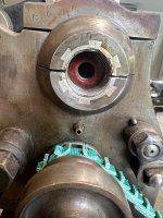
- On the left side of the headstock there is a large threaded sleeve with a hard rubber/plastic washer between it and the main shaft. I assume this is to control end play and was wondering how to adjust this? Picture 5

Would love to find out as much as possible about this. I am sure I will have other questions. Should I start new threads as they come up or just keep this one running.
Thanks in advance
Mike Hayes
 

Attachments

  • F E Reed Lathe (14 of 15).jpg
    F E Reed Lathe (14 of 15).jpg
    519.6 KB · Views: 47
  • F E Reed Lathe (3 of 15).jpg
    F E Reed Lathe (3 of 15).jpg
    338.4 KB · Views: 42
  • F E Reed Lathe (12 of 15).jpg
    F E Reed Lathe (12 of 15).jpg
    433.1 KB · Views: 41
  • IMG_3024.jpg
    IMG_3024.jpg
    362.2 KB · Views: 32
  • IMG_3007.jpg
    IMG_3007.jpg
    426.6 KB · Views: 40
before high speed steel cutters,lathes didnt need much power....Spindle clearance in the bearings of 002/003 isnt too loose,possibly the oil is too thick...always check how the lathe is cutting before making adjustments ,the lubrications of plain bearings is a dynamic situation.....if you have a seizure ,it will make a mess.
 
I have been using straight 30W non detergent oil that I had on hand with modest success. I have vary bad skills in shaping HSS tools so I adapted a small quick change holder to use in it in place of the lantern post. The carbide cutters helped a lot. carbide.
This evening, I tried 0-40 weight engine oil, which is apparently worse and it now shuts down before I start a cut.
I just found some general recommendations on VintageMachinery.org to use oils between ISO 10-68 viscosity. They recommend Mobil DTE hydraulic oil as a generic spindle oil so I will look to get some of that. Not sure if DTE 24 (iso 32) or 25 (iso 46) would be best.
Thanks
 
Mike,

Lots of questions! et me try and answer a few.

30 wt oils should be fine. Non detergent is the first choose. But you should do ok with one with a detergent. It will just clean the grim out very slowly.

A oil is to viscose if the bearing is running hot at high speed with properly adjust bearings. The top speed on that lathe is either 400 or 600 RPM, so a low viscosity oil (ISO 10 or 22) is not needed).

1hp is probably about right. BUT if you have a variable speed motor on it then you are not getting 1 hp at less than rated speed. It would probably be 1/4 hp at 1/2 speed. I'm winging this so I will be corrected.

The back of the spindle housing (left side) is threaded. The part that threads into this sets the axial clearance. There is not real threat bearing in the other direction. Most forces are to the left so it is not an issue. If you are turning with a dead/live center supporting the right side, then it is taking the threat load (when the thrust is to the right).

When babbitt bearings wear, you can adjust them down. But at some point that thrust washer you see in your last picture may touch on the OD. I wonder if that is your problem. If you tighten the bearing caps, but still have several thousands of radial movement, then it is probably the washer.

As John.K pointed out, 2-3 thou is not bad. The advantage of a journal bearing is that it will turn round parts with slop. A ball bearing with .003" total indicated run out will turn parts with .003" of total indicator runout.

Vince
 
P.S. Here is a video of rescraping bearings -


The bearings in the video are more modern version of your bearings, but the principle and materials are the same. My guess is his spindle is a lot harder then yours and does not have any damage (disclaimer: I watched the video 2 years ago and don't remember damage).

What does your bearing look like?

Vince
 
Even though a plain journal has 003 slack/clearance dry and stationary,once the bearing turns with oil in it ,powerful forces are centreing the shaft in the bearing,and there is no longer 003 movement ,but far less in proportion to the load .....I suggest you look into the works of Tower..I think he quoted 700psi as oil pressure supporting the loaded shaft......I also point out that the spindle bearing will starve for oil if clearance is not sufficient ,and seize. A very small clearance will require a very thin oil,such as sperm whale oil.
 
Vince: I went back to the 30W oil and have the bearing caps loose. It is working better again and rotating by hand is easier. I was able to do a bit of work with with a carbide insert on a 1/2" steel rod. I can take a 0.010 - 0.015" cut without shutting down but I can hear the load on the motor. It still occasionally shuts down under no load. It feels the same to me when turning by hand.
- The thrust washer OD is quite loose and there is plenty of room to tighten the bearing. I did back off on how firmly I had it tightened. Thanks.
- The spindle it too heavy for me to easily pull by hand so I have not been able to look at the bearings. I ordered some Dykem High Spot Blue. Once I have that I will get some help to pull it and check the contact. Thanks for the video.
John K: Thanks for the info. I will try to find information by Tower

The lathe came with a new looking 1 HP TECO Westinghouse L510 controller and motor that is set for low voltage. I have never used such a setup and am going to change my focus to understanding how to set it up and use it. I am not confident the controller is configured correctly. The controller is supposed to be rated for 4.3A output but shuts down at about 2.5A with an over current error. Does anyone know if changing the configuration to the high voltage mode would have any advantage?

Another question:
The lever to engage the low speed back gears had an original looking set screw to add tension to the shaft but it was too short and the gears popped out quickly. I was using a small bungee cord to hold it in place but that was a bit sketchy so I added a longer screw to resolve the issue. I am wondering why the existing screw would be short. Would there have been a brass or cast iron plug or in front of it to prevent scoring of the excentric shaft? It does not need to be very tight to keep the gears in place. Just wondering about how this should be set up. See picture.
 

Attachments

  • IMG_3018.jpg
    IMG_3018.jpg
    447.5 KB · Views: 12
I made some changes to the 3 phase TECO controller and got some minor improvements. I can make about a 0.015 cut on steel. A cut of 0.020 caused a current overload when reading about 2.4 amps, which still seems wrong.
I also realized that with some minor changes, I can move the belt to the largest drum on the spindle to get about 25% more torque and run the motor closer to its max speed. I could also put a smaller drum on the motor shaft to get 600 rpm on the lathe with the motor @1750 RPM for a net gain of about 50% in torque.
 

Attachments

  • IMG_3034.jpg
    IMG_3034.jpg
    351.3 KB · Views: 8
Carbide tooling comes in two basic flavours.....positive rake and negative rake.....whats needed is positive rake,as sharp as possible.....any kind of negative rake tooling is actually damaging to an old lathe ,and should never be used......Any idea of heavy cuts is wrong too,you overload the feed mechanism.......which is why I recommend you grind your own cutters.
 
Made an important discovery. The controller/motor combination gives an overload error and shuts down under no load (DRIVE BELT REMOVED). Looks like I need to delay learning about the lathe until I solve some basic electrical/configuration issue. Having spent more time with it the last few days and with the good advice advice above, I was more and more convinced the basic mechanicals were not the issue. However, it has been a while since I debugged something like this and forgot some of the basics of troubleshooting.

Once I get the motor sorted out I will start learning more about the lathe and grinding cutters. When I first got it, I was using the lantern post, which I think adds a level of complexity due to the difficulties of positioning the tool. The carbide I am using has a positive rake. When the motor is working, it was cutting far better than the poor cutters I prepared for the lantern post. I am interested in learning the mysteries of making cutters and have some books on the topic. I have read and understand the basics but do not have enough hands on experience at this point.

If I cannot figure out the motor, I will make a separate post about that issue alone. Many thanks for the advice given above.

Mike Hayes
 
Last edited:
I don't know a lot about those Variable Frequency drives and motors but I would think that your lathe might benefit from an add on transmission between the motor and the spindle pulley to allow the motor to perform in its normal speed range to give you more torque and you could use the electronic drive to give you soft starts or some variation between gear speeds.
There were several makes of these that were often added to lathes like yours that had originally been made for use on an overhead line shaft.
See Post #37 of this thread for more about those types of transmissions
You could probably add one using the bracket that is supporting your motor.
Someone on this forum may have an extra one that they could sell you.
This video of a Dominion Auto Drive transmission was in an earlier post in the thread above.
Jim
 
I think I can get close to matching the motor and lathe max speeds using the larger pulley on the lathe and a slightly smaller motor pulley. If not, I'll keep the option of a step down pulley in mind. Thanks for the video.
 
I've never seen a motor belted directly to an old cone head lathe spindle perform well. Even with a VFD drive, there's always issues of too much speed and/or too little torque. Even if you can't locate an overhead gearbox, IMO, you'll be better off adding a pulley reduction jack-shaft between the spindle and the motor. All the old cone-head belt drives lathes out there would have this either from the factory, or fabricated by the owner, because it's how they were designed to operate. The jack shaft would have a matching cone pulley to give variable speed, and an on/off clutch, but even if you don't need those features, you still need the pulley reduction aspect. The only challenge is deciding where you want to mount it as on the older machines they were often mounted to the ceiling originally, while most shops today want everything mounted to the machine. The old jack shafts are often missing, not because they were not needed, but because someone sold the machine at some point without knowing (or caring) that those separate pieces are part of the kit.

The only lathes that have a motor belted directly to a spindle are either running DC power, or have a complicated VFD set-up to get the right range of speed and torque, and are high end tool and gauge makers lathes (such as Monarch 10EE's). In those cases they want a mechanically smooth and simple transfer of power from the motor to the spindle so there is less "noise" and better surface finish, but those lathes are a different beast than an old tool room lathe. The Monarch forum is full of threads trying to retrofit or repair these systems and IMO it's just not worth the electronics headache if your machine doesn't "need" it.

For reference, think of this lathe like an old South Bend lathe. They either have a jack-shaft behind or under the headstock. That concept is what you are after.
 
FIXED. The previous owner wired the motor coils out of phase. I am surprised it ran at all.

MB Naegle: I moved the motor to the largest cone. My initial tests show a substantial improvement in available torque. With this configuration the lathe will spin at 650 rpm at the max rated motor speed of 1750 rpm. In addition to the "gear" reduction, the larger surface contact of the bigger cone prevents the polyurethane belt from slipping under load. I will keep your advice in mind as I progress in learning more about how to use the lathe and adapt as needed.

Thanks again to all for the advice above which will help me in what to focus on in learning the lathe: bearings, cutters, etc. In its present state, it is a dramatic improvement over my 7 x 14 Micro mark mini lathe. :)

Mike Hayes
 
Interesting. Do you have a link to a source on this and if it states what years this would apply to? There is a description of a simple 10 inch elsewhere on this forum that claims it has Babbitt spindle bearings and a bronze thrust bearing. My lathe is now running well so I have not removed the spindle to see what the bearing is made of. I saw a 1910 catalog that I was tempted to purchase but it is about 10 years older than mine and I am not sure how relevant it would be.

According to info in the book American Lathe Builders:1810-1910 by Cope, mine was made in 1901 or later. That is when the taper turning function was added to the 12" lathe. It also has both belt and gear feeds and the belt feed was supposedly discontinued in 1907. I am still having trouble with the 3 phase motor so am running it in single phase mode with one leg disconnected for now. It works fine for smaller pieces but I have to take lighter cuts for larger diameters. I checked the motor windings with a meter and the all show about 3 ohms, with no measurable leakage to ground. I need to go back and check the phase converter settings again. There is a company nearby that services 3 phase motors so I can bring it to them at some point.
 
Its a Reed Prentice document. So dates to 1912 or later. But looks just like the original F.E Reed 12 inch. They could have used an old drawing but it still has tge belt drive feed also.
 

Attachments

  • 18489 (1).pdf
    1,022.6 KB · Views: 5


Back
Top