What's new
What's new

1943 South Bend 16" x 60" Lathe Resurrection

Great work Tom, looks fantastic! I’m dying to know how the fitting of the spindle for real goes.
Do you have some L00 back plates? Are you planning to switch over all the chucks you have to L00?

I have one L00 backplate now to fit my 8" 3-jaw. My 10" 3-jaw and 10" 4-jaw will both need new backplates. The 3-jaw is a Toolmex Set-Tru (Bison design mfd in Asia) so interchangeable with Bison accessories.

Someday I'll find a good deal on an L00 collet chuck like a Jacobs or Sjogren. I am modifying a JFK 5C lever closer to fit the machine in the meantime.
 
Last edited:
Nice work!, I had L00 on my CLK and loved it. Simple, easy, and accurate.

Thanks! I have been told by more experienced machinists that the long taper centers chucks better than the shallow taper on D1 or A2. The cams are easier, but I don't mind the wrench as infrequently as I need to change chucks. Most of the time I keep a 4-jaw installed.
 
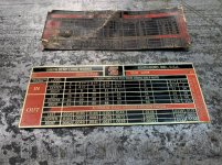
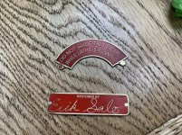
Thomas, thanks for your advice on the nameplates. Here are my first completed attempts. Trick was to use a Black and White Laser printer. A color Laser printer printing black didn't work at all. See the Pulsar guys tech support page for an explanation why. Anyway, happy with these for my first shot.

Note that my lathe gearbox starts at 2 threads per inch. All the others I have seen start at 4 TPI. Needed to make my own.

Erik

2019-03-10 13.55.36.jpg2019-03-10 14.05.58.jpg
 
Last edited:
Thomas, thanks for your advice on the nameplates. Here are my first completed attempts. Trick was to use a Black and White Laser printer. A color Laser printer printing black didn't work at all. See the Pulsar guys tech support page for an explanation why. Anyway, happy with these for my first shot.

Not that my lathe gearbox starts at 2 threads per inch. All the others I say start at 4 TPI. Needed to make my own.

Erik

View attachment 252028View attachment 252029

Hey Erik, congrats on your etching success. Looks great, and I hope you won’t stop at the gearbox plate!

You’ll learn with time how long to leave it in the acid, how to repair a mask that’s starting to fail so you can get more depth, and how to polish the face without damaging the color fill on a shallow etch.

I’d say you’re off to a great start!

Tom
 
What an incredible restoration thread! :)
I recently acquired a 16-24 South Bend and am drawing inspiration from some of the ideas you have detailed here. I know how time-consuming writing out these in-depth threads can be; thank you for explaining the detailed steps you took to perform such a high-class rebuild on your 16" South Bend. (I'm an electrician by trade and particularly admire the route you took to incorporate the updated electrical motor controls. Very nice job!)
 
Glad it gives you some inspiration. Contact me anytime if you get stuck. I have one final fairly major step to go with this lathe before calling it finished, and I hope to document that portion this spring.

Enjoy the journey!

Tom


Sent from my iPhone using Tapatalk
 
We were discussing spindle speeds, speed charts and top spindle speeds in another thread. Having shot my speeds at a top speed of about 1035 rpm, and I'm told a chart reading of 16"ers listing the high end at about 980 rpm.

Thinking of your tach set up, I was checking your thread and watched the vid in post #327. In it, your tach hits real close to 1800 rpm. While not there in person, just listening through vid and hearing spindle belt, I'm wondering if your tach is reading 2x actual speed.

Im thinking your running a vfd where you can manipulate cycles to increase speed, but 1800 seems really really fast.

I was wondering if you had a way to verify that speed, with maybe a hand held tach or some other method.

I can’t say it’s a NASA quality instrument, but I calibrated the tach with a handheld laser tach. You can see it in this Instagram link when I was proofing out the circuit: Tom Utley on Instagram: “It works! Custom #automotive #diesel #tachometer from @speedhut using the #pulse #signal from a #halleffect #gear tooth #sensor. I could…”

Also, I’ll reiterate, I don’t recommend running high speed for long periods or under heavy cutting pressures. For an occasional high speed finishing pass on small diameter workpieces, though, I believe it won’t hurt the machine.


Sent from my iPhone using Tapatalk

While I know some speed manipulation can be done with a vfd, I would not have guessed so great.

For perspective, I do some power generation work where a diesel engine turns a generator end, which is very like and electric motor. The engine speed is directly tied to cycles or hertz. Depending on the gen end's internal setup, with how many poles inside, it is designed to reach a certain hz at a given rpm range.

In the USA we use 60hz. The two most typical gen ends are designed to reach 60hz at either 1800 rpm or 1200 rpm. For 1800 rpms, every cycle/hz is equal to 30 RPM's. 60hz x 30 = 1800. For 1200 rpm gens, its 20 rpms for every cycle. 60hz x 20 =1200 rpm.

In dealing with mechanical engines (not electronic controlled fuel system), I generally set speeds to 60.5hz or 61hz. We do this to help engine recovery when a hard load is applied to electrical system, like someone turning on a higher hp electric motor. This way gen set runs no-load at 61hz, but when sudden load is applied, the rpms only dip down to 60hz.

As part of what I do, many packages are set up with protections to immediately shut engine down if there is a problem. One of those protections is overspeed. The overspeed protection is not just for electric spike protection, its there to keep engine and gen end from blowing apart.

I actually hate running those tests. I like 63.5 to 64hz trip points. But often I see 65hz or more in testing. I gotta tell you, when you're next to it, and hitting those speeds, your butt really tightens. It just sounds really unnatural, and I'm waiting for the big bang, lol.

And just thinking of that, 65 cycles, on an 1800 rpm rating, that's only 1950 rpm. That's less than 10%.

Assuming normal lathe spindle top speed at 1000 rpm, and if your electric motor is rated 1800 rpm. To hit 1800 rpm spindle speed, man your motor must be hitting 3000 plus rpms. Wow, that's crazy. I'd really not guess you could do that kind of percentage increase without pieces flying.
 
While I know some speed manipulation can be done with a vfd, I would not have guessed so great.

For perspective, I do some power generation work where a diesel engine turns a generator end, which is very like and electric motor. The engine speed is directly tied to cycles or hertz. Depending on the gen end's internal setup, with how many poles inside, it is designed to reach a certain hz at a given rpm range.

In the USA we use 60hz. The two most typical gen ends are designed to reach 60hz at either 1800 rpm or 1200 rpm. For 1800 rpms, every cycle/hz is equal to 30 RPM's. 60hz x 30 = 1800. For 1200 rpm gens, its 20 rpms for every cycle. 60hz x 20 =1200 rpm.

In dealing with mechanical engines (not electronic controlled fuel system), I generally set speeds to 60.5hz or 61hz. We do this to help engine recovery when a hard load is applied to electrical system, like someone turning on a higher hp electric motor. This way gen set runs no-load at 61hz, but when sudden load is applied, the rpms only dip down to 60hz.

As part of what I do, many packages are set up with protections to immediately shut engine down if there is a problem. One of those protections is overspeed. The overspeed protection is not just for electric spike protection, its there to keep engine and gen end from blowing apart.

I actually hate running those tests. I like 63.5 to 64hz trip points. But often I see 65hz or more in testing. I gotta tell you, when you're next to it, and hitting those speeds, your butt really tightens. It just sounds really unnatural, and I'm waiting for the big bang, lol.

And just thinking of that, 65 cycles, on an 1800 rpm rating, that's only 1950 rpm. That's less than 10%.

Assuming normal lathe top speed at 1000 rpm, and if your electric motor is rated 1800 rpm. To hit 1800 rpm spindle speed, man your motor must be hitting 3000 plus rpms. Wow, that's crazy. I'd really not guess you could do that kind of percentage increase without pieces flying.

My motor is a 3-phase 3hp Leeson. I have the VFD max frequency parameter set at 90Hz to protect the drivetrain and the chuck. At this frequency, with the combination of sheaves I have in the underdrive/countershaft, I top out just shy of 1800RPM if I were to crank the potentiometer all the way up.

I haven’t done the math, but the max RPM at 90Hz tells me I’d run around 1200RPM at 60Hz. That’s a little faster than how it came from the factory, but the original 1.5hp motor pulley was smaller.


Sent from my iPhone using Tapatalk

I'm not 100% sure either. In general, motors in the US rated at 60hz come in speeds around 1200, 1800, and then 3600 rpm's, depending on poles insides. I'm guessing your motor is rated 1800 rpm at 60hz. If that's right, at 90hz the motor is pushing 2700 rpm.

I recall you had repair to bearings for lower cone pulleys. Not sure if the vee pulley portion of that is the same, but I would guess it's the same diameter.

Also not sure what your current motor pulley diameter is. But there's a pretty cool calculator for anyone interested. It can help at least ball park some changes, though my head might hurt figuring in the total from motor through spindle, lol.

Pulley Calculator. RPM, Belt Length, Speed, Animated Diagrams

My usable diameter on motor pulley is roughly 3.5". I would guess our vee pulleys diameter the same on cone pulley. Not sure our exact ratio is the same on highest step of cone pulley. But if your thinking you hit 1200 spindle speed at 60hz, then it must be a higher ratio than mine, as I hit 1035 rpm spindle speed.
 
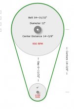
Just an update. After measuring the larger vee belt pulley, above motor pulley, at 12". I had ran the numbers on mine. I figured out that top spindle speed is double what that 12" pulley turns. Thinking your larger pulley is also 12", I played with the slider on calculator and the numbers matched what we talked about if I put your motor pulley to 4". Again using this link:
Pulley Calculator. RPM, Belt Length, Speed, Animated Diagrams

With a 4" pulley turning 1800 rpm at 60 cycles, the larger pulley turns 600 rpm, doubling it puts spindle speed at 1200 rpm like you thought.

Now 90hz multiplied by 30rpm per cycle equals 2700 motor rpm. Changing rpm on that calculator to 2700 rpm, raises large pulley speed to 900 rpm, doubling that, equals 1800 rpm on spindle, just like we see on your tach.

82.jpg


Back
Top