What's new
What's new

Help Needed Understanding/Identifying this Buck Boost Transformer

dalmatiangirl61

Diamond
Joined
Jan 31, 2011
Location
BFE Nevada/San Marcos Tx
Pics 1-5 are left to right as seen below, ignore numbering I assigned to them as I downloaded them.
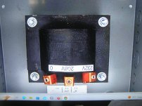
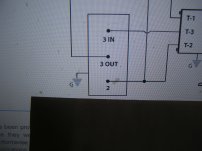
Pic 1. The transformer I need, that I think dealer wants too much $$ for. Pic 2. Schematic for wiring transformer in pic 1 as a buck transformer.

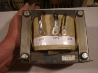
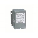
Pic 3, a transformer I found that I think will work, and think is the same as transformer in pic 1.
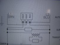
Pic 4, schematic the mfr used for transformer in pic 3, they used it as a boost transformer.
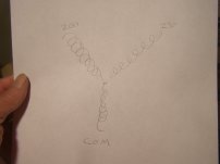
Pic 5, using an ohmeter I see continuity between all 3 leads, I've drawn it as a star connection, but that might not be right.

The questions: I'm not understanding how if there is continuity between all 3 leads this is not going to be a dead short leading to an awesome spark show? What would be the correct name for this type of transformer? Searching "buck boost transformer" I get a million hits for multi lead transformers, and none showing the type pictured here.
 

Attachments

  • buck boost 1.JPG
    buck boost 1.JPG
    1.5 MB · Views: 27
  • buck boost 5.JPG
    buck boost 5.JPG
    1.3 MB · Views: 26
  • buck boost 2.JPG
    buck boost 2.JPG
    1.1 MB · Views: 25
  • buck boost 3.JPG
    buck boost 3.JPG
    1.3 MB · Views: 25
  • buck boost 4.JPG
    buck boost 4.JPG
    1.2 MB · Views: 25
This seems to be an autotransformer.
That is a transformer with one winding and taps into that winding. You might be familiar with a Variac, which is an autotransformer with an adjustable tap.

An autotransformer clearly does not provide isolation from the line, so you need to take that into account.

The measured DC resistance might be low, but the AC impedance should result in normal currents as in any transformer.

John
 
Last edited:
This seems to be an autotransformer.
That is a transformer with one winding and taps into that winding. You might be familiar with a Variac, which is an autotransformer with an adjustable tap.

An autotransformer clearly does not provide isolation from the line, so you need to take that into account.

John
The unit in pic 3 is labeled autotransformer in the schematic in pic 4, but that is not what the company that sells unit in pic 1 calls it. When I search autotransformer nothing like this shows up, just variacs.
 
The unit in pic 3 is labeled autotransformer in the schematic in pic 4, but that is not what the company that sells unit in pic 1 calls it. When I search autotransformer nothing like this shows up, just variacs.

They're certainly not as common as transformers with independent isolated windings. But they can be less costly to make, so may be used in some specific applications that don't need isolation.
 
I agree with JBTR, those are autotransformers. and are not doing what we normally consider to be "buck" or "boost".

They are shown hooked up to change the voltage that you get between 2 legs of a 3-phase circuit, but they should also work in a single-phase setup.
 
I agree with JBTR, those are autotransformers. and are not doing what we normally consider to be "buck" or "boost".

They are shown hooked up to change the voltage that you get between 2 legs of a 3-phase circuit, but they should also work in a single-phase setup.
That brings me back to the problem, the internet is not giving me results that look like the 2 units I pictured above, I get variacs and multi terminal buck boost transformers like what is pictured below, and that is not what I want. I can only assume I'm using the wrong search term. Where, how can I find units as pictured above?
 

Attachments

  • autotransformer.jpg
    autotransformer.jpg
    41.1 KB · Views: 7
When the multi-terminal units are wired for buck or boost, the net result is exactly what a permanently wired autotransformer is..... one larger winding, with a tap.

The question is whether the unit you have is intended for that sort of usage, or if it is made for a different purpose. Those seem to be intended for buck/boost, so that's OK.

The next question is current or VA rating, which I did not see.

One of those will take 208V in and output 232V, or, take in 232V and output 208VAC. They work either way, autotransformers are normally reversible.

You hook the labeled connection to the labeled voltage, and the other connection then puts out it's labeled voltage, whatever those are.

They also work at voltages lower than marked, although the VA rating will change (the current rating stays the same). In that usage, the ratio between voltages stays the same, but the voltages are proportionally lower.

The last picture is not what they are. There would be only two windings (coils), with a tap between them.

Almost any transformer will work as an autotransformer if hooked up correctly. So you are not necessarily stuck with those choices, depending on what power you need.

There is a world of transformers out there, of all different voltages on input and output, and all sorts of power ratings.

If, for instance, you have 230VAC, and a transformer that takes 230VAC and outputs 20 volts at 10A, then if can be used to make 250VAC from the 230VAC, or 230VAC from 250VAC. And if so used, the load current can be up to the 10A rating of the low voltage winding.

Clear as mud?
 
Yes, its all clear as mud right now:).

Humor me, I know there are many ways to do this with other transformers, I've done it, but quite honestly, it looks like a science project, and if it ever gets inspected I don't want to start getting into electrical theory. Using the 3 terminal transformer as pictured in first post will be nice and neat, and I might even slap a fake label on it for good measure:D.

The transformer I need, first pic, they want $1400 for it, is rated 50A on 230v 1ph, not sure if that is actual mfr rating, or the aftermarket co rating, its in a 10" x 10" box. Pic 3, found on ebay has no ratings on it, I was able to trace it to having been used in an air conditioner to run a 230v unit on 208v, spec chart for AC says 23 amps. Dimension wise its as big as the one in pic 1, I think.... and it was $100. If its the same thing, it should work, and I'm not pulling anywhere near 50A yet.

I think the aftermarket seller is blowing smoke calling it proprietary, I don't think they really cost $1400, I think they are something available off the shelf in a selection of sizes and ratings, but I can't find them.

Awander
The goal is to buck voltage on rpc generated leg down so it quits tripping overloads in machines, for less than $1400:D. Pic 1 is their fix, I'm just trying to copy it using what I think is the same item. I'm leaving their name out of this discussion because my goal is not to trash talk them. Edit: The one you linked to is NOT the style I'm looking for, I want the style in pics in first post.

I'm still not clear on why L3 and L2 meeting inside transformer is not a spark show?
 
Last edited:
So, "buck" is not really what you are trying to do here.

A buck transformer actually uses a winding of a transformer, wired in reverse polarity in series with another winding of the same transformer, to drop the voltage on that second winding.

Boost is the same, except that you wire the 2 windings in phase, instead of opposing each other.

Is your generated 3-phase system a star or a delta system?
 
A buck transformer actually uses a winding of a transformer, wired in reverse polarity in series with another winding of the same transformer, to drop the voltage on that second winding.

Is your generated 3-phase system a star or a delta system?
That is what I want to do, reduce voltage on L3, the generated leg, only the generated leg. I think its delta.
 
Transformers are basically made with two core types: E-I stampings (literally stamped sheets of silicon steel in the shape of the letters E & I, stuck together and laminated) or toroidal (stamped rings, laminated). Which is used doesn't usually matter for the electrical application; it's mostly a manufacturing and packaging consideration.

You seem to be concerned about open vs enclosed transformers.

Connecting a standard 24VAC control transformer (of about 1.25kVA capacity) with the 24V winding in anti-series with the primary winding should give you the right ratios with much easier availability and cost - they're everywhere for HVAC purposes. With a 240V primary, you'd get 240:216V, or about 230:207V. Most will have a couple of primary taps to be adjustable.
 
Toroidal cores are usually wound from strip, but it makes no difference to the result, apart from making less waste.

The OP is talking about the "generated leg", presumably from an RPC.

I am not sure why the voltage is high, usually it is low. Capacitors are often used to boost the voltage. So I am thinking that the system may be overcomplicated and may not work well...... See below.

Assuming the reduction really is needed, then: To do the reduction, a suitably rated autotransformer (or properly wired normal transformer) is connected from the 240V neutral to the generated leg. The neutral is balanced in the source to the RPC, and is usable as a reference.

The autotransformer is connected with the full winding (rated for the L3 voltage) from neutral to L3, and the reduced voltage tap is then the new output. The tap end of the full winding should be connected to L3.


It works the other way as well. Since the L3 is normally lower coming from the RPC, you can use an autotransformer to boost the L3 voltage to equal the input voltage.

I would not combine the transformer with the use of capacitors. Capacitors are an alternate way of boosting the L3 voltage, but are less stable, so the advantage of using a transformer is pretty much lost. There is no advantage to boosting with capacitors and then reducing to a usable voltage with a transformer.

To replace the boost capacitors using the transformer as a boost, you would connect as above, but connect the TAP to the L3 voltage, and the high end of the winding would be the new L3 output. Again, the boost should be to 5% or so over the incoming voltage. Maybe a bit more, but not over 10%.
 
You seem to be concerned about open vs enclosed transformers.
No, you've missed the point altogether. I clearly identified the questions in first post, instead of answering those questions y'all want to suggest other ways to achieve the same goal, I don't want to try other ways, I want to figure out what off the shelf transformer the mfr is asking stupid money for to fix the poor design rpc they sell.

Repeat:
The questions: I'm not understanding how if there is continuity between all 3 leads this is not going to be a dead short leading to an awesome spark show? What would be the correct name for this type of transformer? Searching "buck boost transformer" and "autotransformer" I get a million hits for multi lead transformers, and none showing the type pictured here. WHERE CAN I FIND TRANSFORMERS IN DIFFERENT SIZES JUST LIKE THE TRANSFORMERS PICTURED IN THE FIRST POST? LINKS IF YOU'VE GOT THEM.
 
JST
The generated leg runs high, yes there are capacitors, in another thread a year or so ago I experimented with removing some of them, I see no reason to repeat those failed experiments. Pic 1 in post 1 above is the mfr recommended fix to the problem, a transformer with only 3 taps, labeled 238V/208V/0. I want to figure out exactly what that transformer is, and where to find one, besides ebay where the sellers cannot provide specifications for them.
 
That is what I want to do, reduce voltage on L3, the generated leg, only the generated leg. I think its delta.
I understand that you want to reduce the voltage you get on L3. What I am saying is that you won't do it by "bucking", because that is not what that transformer does.
 
Well, it sure looks like the transformers in the first 2 pictures are Autotransformers-or isolation transformers wired internally to look like Autotransformers.

Just for reference, this is an Autotransformer with the voltages of the units you pictured:
AUTOTRANSFORMER.png

I can't say for sure if it would do what you need, when hooked up as labelled, between L2 and L3. I'm no expert on 3-phase systems.

I'd follow Jerry's advice above: "To do the reduction, a suitably rated autotransformer (or properly wired normal transformer) is connected from the 240V neutral to the generated leg. The neutral is balanced in the source to the RPC, and is usable as a reference."


So the question becomes, how much too high is the generated leg? (in other words, how much voltage are you trying to knock off of it?)

And how many amps do you need to pull?


Just for reference, again, the hookup above is not a "buck" or a "boost" setup. It's just an autotransformer.

Buck/Boost looks like this:
BUCK-BOOST.png


Back
Top