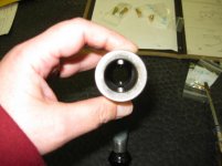
I like that bearing in the carriage for what must be dial, and/or crossfeed screw. That's a bit better than what was original on my Monarch 61, I had to make a bushing as the parts had wear and slop.
What I really love is those oilers in the cross slide for the compound. Hard for me not to compare, as my machine is a 1956 and they are roughly the same class of machine but a different swing, same rpm spindles too.
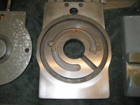
I've had some distractions, so I've had a little break from my build, but the compound is the part I'm working on, on mine. No oilers, but I have a drain passage coming out the side cross slide, presumably to let coolant out, instead of being trapped under the compound. But even still, years of coolant or condensation has left the cast iron of mine not looking great:
View attachment 348347
I don't have pics yet, nor posted, but I started machining the top surface of that cross slide. After initial machining, the surfaces covered by compound begin to show surface rust, while the rest does not. Makes me think I might have miniscules amount of water in pores of cast iron. And its in a dry environement. . .
Been thinking of baking it in an oven for a little while, or how to handle it.